In the process of establishing a connection between multiple devices in a microcontroller, the data and address line of every single device would take up important pins in the microcontroller which leads to more traces on the PCB board. And also it requires more components which further results in cost enhancement of the system and they are even easily subjective to noise and intrusion. So, to stay back from this complication Philips introduced IC buses which were also called I2C in the year the 1980s. So, today the main agenda of this article is to focus on giving an introduction to the I2C protocol, how it works, it’s programming and many other concepts related to it.
What is I2C Protocol?
I2C is termed as the abbreviated form of Inter-Integrated Circuit. This is a type of communication bus which is mainly designed and developed to establish inter-chip communication. This protocol is a bus interface connection that is embedded into multiple devices to set up serial connections. I2C is considered to be the most prominent chip-to-chip communication protocol as it holds the features of both UART and SPI.
The features of the I2C protocol are:
In this protocol two-way communication is possible and it is half-duplex
- Information transfer happens in the form of blocks or frames and it can be configured in a multi-master approach
- Clock stretching takes place which means when the slave device is not in the condition of accepting more data, then the clock is stretched making the SCL signal to LOW therefore master gets disabled to raise the CLK signal. The master signal does not raise the CLK signal as the wires are connected in AND format and have to wait till the slave releases the SCL line making sure that it is ready to send the subsequent bit.
- It follows a simple approach for validation of data transfer
- Using two shared bus lines, any device on the I2C network can be controlled
- Adjustment of data transfer can happen at any point of time which makes sense for no prior agreement like in UART protocol

Master-Slave Communication in I2C
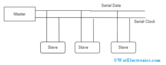
This is a multi-slave and multi-master communication protocol that gives the flexibility of connecting multiple IC at a single instance of time to a single bus. In general, in I2C devices, the master takes the initiation of establishing communication whereas in the case of multi-master, only one master holds the possession of setting up communication.
I2C Protocol Working Principle
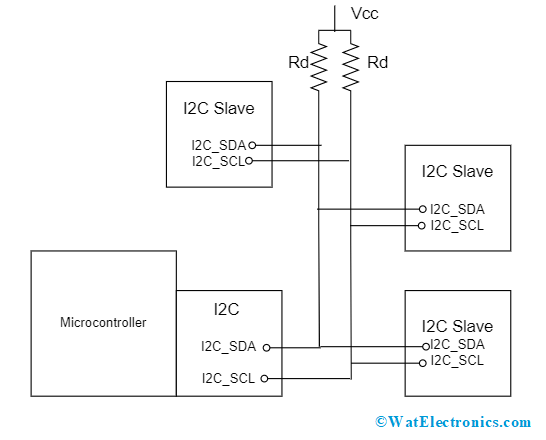
The working of the I2C communication protocol happens through open drain lines which are Serial Data (SDA) and SCL (Serial Clock). Initially, both the SDA and SCL lines are pulled high and the bus mainly functions in two modes which are Master and Slave.

Message Format in I2C
Every bit which is transferred on the serial data line gets synchronized by HIGH to LOW pulse for every clock signal that is received on the serial clock. The SDA line will not change when the SCL is in a HIGH state and it is changed only when SCL is in a LOW state. As discussed SDA and SCL are open-drain lines, they require of pull-up resistor to make them high as because the devices on the bus are in the active LOW state.

I2C Protocol Architecture
Here, data transfer takes place in the form of packets and each packet consists of 9 bits. The sequence of bits is shown below:
Start and Stop Bits
The switching of serial data line takes place from high to low voltage level and low to high voltage levels before and after the serial clock line switches from HIGH to LOW and LOW to HIGH. The below picture shows the switching of SDA and SCL lines.

Timing Diagram
Address
This is the immediate frame after the start bit. The master bit transfers the slave’s address with which it has to communicate to each slave that was connected to it. Then the slave bit compares its own address with the address of the slave that was sent by the master. When both the addresses match, it transmits a low voltage ACK signal to the master signal. Whereas when both the addresses do not match, the slave remains idle and the serial data line stays at HIGH.
Read/Write
When the Read/Write indicates ‘1’, then the master is transmitting data to the slave whereas when Read/Write indicates ‘0’, then the master is receiving data from the slave signal.
ACK/NACK
The acknowledge/no-acknowledge bit is the subsequent bit of every frame in a message. When data/address was successfully transmitted, then the ACK signal gets back to the sender from the receiver device.
Data Frame
When the ACK bit is detected by master from slave it indicates that the first data frame can be transferred. This data frame is of 8-bit length. After the data frame, ACK/NACK bit detects the successful transmission of the frame. Once the transmission was successful, then the next data frame will be ready to transmit.
Please refer to this link for I2C Protocol MCQ
Once all the data frames are received, the master sends the STOP signal indicating to stop the transmission.
The below I2C protocol timing diagram gives a clear idea of the working of the protocol.
I2C Protocol Programming in C for 8051
Interfacing of I2C protocol EEPROM with 8051 is not hard. The functionality of interfacing is to transmit WRITE signal and then data/address buses. Here, EEPROM is used for data storage. The lines in EEPROM are managed by the I2C protocol-supported drivers. Through serial clock and serial data lines, the RD/WRT activities of EEPROM are performed. Here, is the C code for interfacing.
#include <reg51.h>
unsigned char bdata EP_DATA;
send_bit lsb = EP_DATAɅ0;
send_bit msb = EP_DATAɅ7;
send_bit SDA = P3Ʌ7;
send_bit SCL = P3Ʌ6;
unsigned char rec[12];
void i2c_START(void);
void i2c_STOP(void);
void i2c_SEND(unsigned char);
void i2c_SEND_BYTE(unsigned char addr, unsigned char data);
void i2c_SEND_STRING(unsigned char addr, unsigned char *s);
unsigned char i2c_READ(void);
unsigned char i2c_READ_BYTE(unsigned char addr);
unsigned char i2c_READ_STRING(unsigned char addr);
void ser_init;
void tx(unsigned char SEND);
void tx_str(unsigned char *s);
void i2c_START(void)
{
SDA = 1;
SCL = 1;
SDA = 0;
SCL = 0;
}
void i2c_SEND (unsigned char SEND);
unsigned char i2c_READ (void)
{
unsigned char i;
lsb = SDA;
for (i=0, i<=7, i++){
EP_DATA=EP_DATA<<1;
lsb = SDA;
SCL = 1;
SCL = 0;
}
if (EP_DATA ==13){
SDA =1;
SCL =1;
SCL=0;
SDA=0;
i2c_STOP();
return (EP_DATA);
}
SDA =10
SCL =1;
SCL=0;
SDA=1;
return (EP_DATA);
}
void(i2c_STOP)
{
SDA =0;
SCL =1;
SDA=1;
SCL=0;
}
void i2c_SEND_BYTE(unsigned char addr, unsigned char data);
{
i2c_START();
i2c_SEND(0×a0);
i2c_SEND(addr);
i2c_SEND(data);
i2c_STOP();
}
unsigned char i2c_READ_BYTE(unsigned char addr);
{
i2c_START();
i2c_SEND(0×a0);
i2c_SEND(addr);
i2c_START();
i2c_SEND(0×a1);
REC=i2c_READ();
i2c_STOP();
return REC;
}
void i2c_SEND_STRING(unsigned char addr, unsigned char *s);
i2c_START();
i2c_SEND(0×a0);
i2c_SEND(addr);
while(*s){
i2c_SEND(*s++);
}
i2c_STOP();
}
unsigned char i2c_READ_STRING(unsigned char addr);
{
unsigned char i;
i2c_START();
i2c_SEND(0×a0);
i2c_SEND(addr);
i2c_START();
i2c_SEND(0×a1);
for (i=0,i<10,i++){
rec[i]=i2c_READ();
}
i2c_STOP();
return rec;
}
void ser_init()
{
SCON=0×50;
TMOD|=0×20;
TH1=0×FD;
TL1=0×50;
TR1=1;
}
void tx(unsigned char send)
{
SBUF=send;
while (TI==0)
TI==0;
}
void tx_str(unsigned char *s);
{
while(*s)
tx(*s++);
}
int main()
{
unsigned char data[12];
ser_init();
i2c_SEND_STRING(0×00, “WATELECTRONICS”);
i2c_READ_STRING(0×00);
tx_STR(rec);
while(1);
}
I2C Protocol Arduino
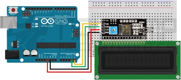
This section explains I2C protocol communication on the Arduino board. To establish the communication, the serial data and serial clock signals are connected to A4 and A5 pins on the board. For the communication to happen, two Arduino UNO’s along with 2 LCD displays are connected together.
Potentiometers are used at each Arduino board in order to know the transmission values from master to slave and vice versa. So, by altering the potentiometer, values can be determined. Few of the wiring library functionalities to be known here are explained below:
Wire.begin(address) – This initiates the wiring library and connects the bus either as master or slave.
Wire.read() – Used to read the information which was received either from slave or master device.
Wire.write() – Used to write the information to slave or master device.
Wire.beginTransmission(address) – With the provided slave’s address, this library initiates the transmission to I2C components.
Wire.endTransmission() – It is used to end the transmission which was initiated by beginTransmission().
Wire.onRequest() – This library is called when the master requests information from the slave device.
Wire.onReceive() – This library is called when the slave receives information from the master device.
Wire.requestForm(address, quantity) – This library helps when the master requests bytes from the slave.
At pin A0, analog input is provided which ranges between 0V – 5V, and convert the analog value to digital value (0 to 1023). The converted value is further converted to 7-bit values (0 to 127) because only 7-bit information is transmitted for I2C communication. And the next process takes place at A4 and A5 pins of Arduino.
Specifications
The specifications allow manufacturers to design I2C devices to be in compatible with the bus requirements. Below is the I2C protocol specification which is generally considered:
- The clock frequency for Serial Clock has a minimum of ‘0’ and a maximum of 400-1000kHz
- The data setup time in the fast mode operation is 50 ns
- The data validation time ranges between a maximum of 0.9 – 0.45 µsec
- The data validation acknowledgment time ranges between a maximum of 0.9 – 0.45 µsec
- The noise margins at the HIGH and LOW levels are 0.2VDD and 0.1 VDD volts
- The rising time of serial data and serial clock signals has a minimum of 20 ns and a maximum of 300 ns
- The falling time of serial data and serial clock signals has a minimum of 20 ns and a maximum of 300 ns
- The capacitive load at every bus is 400pF
- The time where the bus is free between STOP and START conditions is a minimum of 0.5µsec
Difference between UART, SPI and I2C
The below tabular column compares the features of various kinds of interfaces by considering multiple aspects such as the interfaces data rate, type of communication, complexity, and many others.
| Feature | I2C | UART | SPI |
| Termed as | Inter-Integrated Circuit | Universal Asynchronous Receiver/Transmitter | Serial Peripheral Interface |
| Type of Transmission | Synchronous | Asynchronous | Synchronous |
| The maximum level of Speed and Distance | 1Mbps and 0.5 mts | 115.2Kbps and 15 mts | 4Mbps and 0.1 mts
|
| Pins | SDA – Serial Data
SCL – Serial Clock |
TxD – Data Transmit
RxD – Data Receive |
SS – Select Slave
MISO – Master Input and Slave Output MOSI – Master Output and Slave Input SCLK – Serial Clock |
| Clock | I2C has one clock signal between multiple slaves and masters | There is no common clock signal. There will be three independent clock signals | A common serial clock signal exists between slave and master devices |
| Software Addressing | In the I2C interface, 27 or 210 slave devices can be addressed |
No addressing is required | In order to address slave that is connected with master, slave select lines are used |
| Complexity of Hardware | More complex | Less | Less |
Advantages and Disadvantages
The I2C protocol advantages and disadvantages are as follows:
Advantages
- Even though there are multiple devices on the bus, the signals required are less
- It has the ability to support many masters
- It has enhanced adaptability where the requirements of various slave devices can be achieved
- It has multiple-master and multiple-slave flexibility
- I2C protocol has no complications in design
Disadvantages
- I2C protocol is designed with an open-drain configuration where it limits the speed and also pull-up resistors are used which further lessens the communication speed
- It needs more space
Applications of I2C Protocol
The applications of Inter-Integrated interface can be found in the devices that operate at less speed. A few of those are:
- Hardware sensors
- Used in communications having multiple micro-controller
- Employed in the assessment of ADC and DAC circuits
- Used in EEPROM devices
Please refer to this link to know more about Network Protocol & Modbus.
Know more about I2S Protocol MCQs, Sensors MCQs & Wireless Sensor Network MCQs.
This is the whole concept of the I2C protocol. This article has focused on explaining the I2C protocol definition, working, timing diagram, advantages, and applications. Know further on how I2C protocol Verilog code can be written?
