A hot wire anemometer is one kind of device, used to measure the speed and direction of the wind. These are used as wind speed instruments in the meteorology sector. In the 15th century, Leon Battista Alberti invented the first mechanical anemometer. After several modifications, John Thomas Romney Robinson in 1846, improved the design by using cups and mechanical wheels.
Anemometers are classified into two types like pressure type and velocity type. The hot wire anemometers are the velocity type anemometers that are used to measure the direction and instantaneous velocity of the fluid stream. This article describes the principle of a hot wire anemometer and its working.
What is Hot Wire Anemometer?
Definition: Hot Wire anemometers are one of the types of thermal anemometers used to measure the direction and velocity of the fluid stream by measuring the heat loss of the wire, which is kept in a fluid stream. Since the electric current is passed to heat the wire. The hot wire anemometer is used in fluid mechanics as a research tool.
The working principle is based on the change in temperature of the wire, which is from high to low. It determines the relationship between the resistance of the wire and the wind speed. It is used to measure the speed of the wind by placing the sensor in the wind stream that is to be measured. The instantaneous velocity of the fluid can be determined from the voltage measurements.
The hot wire anemometers are classified into two categories. They are,
- Constant current anemometer
- Constant temperature anemometer.
The hot wire anemometer is delicate with a high-frequency response and excellent spatial resolution. The measurement of the rate of cooling of wire can be done in either turbulent flows or any liquid stream with velocity fluctuations. In some cases, the direction of the wind cannot be determined unless the hot wire anemometer is coupled with the wind vane.
The commercial hot wire anemometers are available with a flat frequency response of up to 17KHz (<3dB) at an average velocity of 9.1m/sec
Hot Wire Anemometer Circuit Diagram
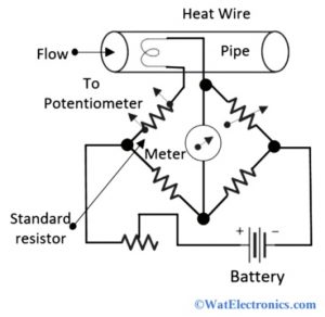
The basic hot wire anemometer circuit diagram is shown below.

Hot Wire Anemometer Circuit Diagram
The heat wire/hot wire is placed in a pipe filled with a fluid gas stream. The leads taken out from the wire are connected to the Wheatstone bridge to measure the variation in resistance of the wire. The deflection pointer of the galvanometer helps to measure the flow rate when calibrated.
The principle of a hot wire anemometer is based on the rate of cooling of the hot wire by the wind speed. This can be determined by using either the constant temperature method or the constant current method as discussed below.
The working of a hot wire anemometer is simple. When the hot wire is kept in a liquid-gas stream, the heat gets transferred from the wire to the gas. Therefore the temperature of the wire decreases and changes in resistance of the wire. This variation in resistance of the wire is utilized in the measurement of the flow rate of the liquid stream.
Construction of Hot Wire Anemometer
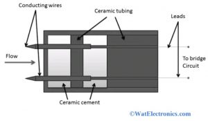
The basic hot wire anemometer comes with two probes with a thin wire stretched between them. The thin wire gets heated up by the anemometer to a certain known temperature. When the wind is passed through the wire, it begins to cool down. This instrument is used to determine the speed of the wind by measuring the loss of heat of the wire. Since the sensor is placed in the wind stream, which is to be measured.

Construction of Hot Wire Anemometer
The two important parts necessary for the construction of a hot wire anemometer are the Wheatstone bridge and Conducting wires. The conducting wires are connected inside the ceramic body of the anemometer. The leads taken out from the ceramic body are connected to the Wheatstone bridge, to measure the variation in resistance of the wire. The basic hot wire anemometer circuit diagram is shown below.
Working of Hot Wire Anemometer
The working of a hot wire anemometer can be explained in two ways to measure the flow rate. They are,
- Constant current method
- Constant temperature method
Constant Current Method
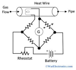
In this method, the anemometer is kept in the fluid gas stream to measure its flow rate. The current at a constant magnitude level is needed to be passed through the wire. The voltage level of the Wheatstone bridge should be constant. The circuit diagram of the hot wire anemometer with the Wheatstone bridge is shown below.

Constant Current Method
The heat gets transferred from the wire to the fluid stream when the wire is kept in the fluid stream. The change in heat changes the resistance of the wire. That means the heat and the resistance of the wire are directly proportional. If the heat is reduced, then the resistance of the wire decreases automatically.
The variation in the resistance is measured by using the Wheatstone bridge, which is equal to the flow rate of the fluid. The wire used in the operation of the hot wire anemometer is also known as sensing wire. Observe the galvanometer deflection to measure the flow rate of the gas when calibrated.
Constant Temperature Method
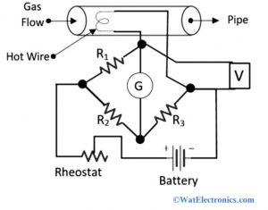
In this method, the heating of wire is done through an electric current. When the hot wire is placed in the liquid gas stream, the heat gets transferred from the wire to the liquid. Then, the change in temperature of the hot wire changes its resistance. The principle of working is that the temperature and the resistance of the wire should remain at a constant level.

Constant Temperature Method
Hence the current passing through the wire is increased to get back the resistance and temperature of the wire to their initial position. The measurement of the flow rate of the gas is equal to the total current required to bring back the resistance and temperature of the wire to the initial condition. The circuit diagram of a hot wire anemometer with a constant temperature method is shown below. The voltmeter is connected across the bridge circuit to determine the resistance variation from the voltage measurements.
Advantages
The advantages of a hot wire anemometer are listed below.
- The electronic components used in the design are at affordable rates and accurate
- It offers high sensitivity
- The spatial resolution of the hot wire anemometer is excellent.
- The provides a high-frequency response. That is greater than 10KHz
- It can operate at high temperatures
- The instrument is small and its operation is very simple because there is no additional sensor.
- It has data handling capabilities to collect meaningful data.
- The ratio of signal to noise is low.
- There is a possibility of high flow rates of the fluid.
- It is a well-established, reliable, and accurate device.
- It can measure turbulent and laminar flows.
Disadvantages
The few disadvantages of hot wire anemometer are,
- It is a fragile type device and can be used only in clean gas fluids.
- Recalibration of a device is necessary due to the accumulation of dust.
- The turbulence intensity is high
- The probes of the instrument might break.
- Contamination issues
- Heat transfer issues between the probe and the surface
- The pointer deflection issues due to the change in atmospheric temperature.
- The power required to operate the device is more.
Hot Wire Anemometer Equation
In a hot wire anemometer, the heat to the wire is transferred electrically when it is placed in the fluid stream. The temperature of the wire with resistance is measured by using a Wheatstone bridge. To measure the heating current, the temperature of the wire should remain constant. In this case, the bridge goes to a balanced condition. Consider the hot wire anemometer circuit diagram as shown above to derive the heat flow velocity equation.
The standard resistor and the heating wire are connected in series with each other. From the value of voltage drop across the resistor, the current across the heating wire is obtained. However, the potentiometer is used to measure the voltage drop value across the resistor.
To determine the heat loss from the heating wire, the following equation is used.
That is, a(vρ + b) ^½ J/s
Where ‘v’ is the heat flow velocity
‘ρ’ is the fluid density
‘a’ & ‘b’ are the constants, in which their value depends on the dimension and physical properties of wire and fluid.
Let ‘I’ be the current of the heating wire.
‘R’ be the resistance of the wire.
At balanced condition, generated heat is equal to the loss of heat.
That is,
I2R = a(vρ + b) ½
v = [I2R / (a2 – b)] / ρ
The temperature and the resistance of the hot wire anemometer are kept constant for the measurement of fluid rate by current I measurement.
Applications
Some of the applications of hot wire anemometers are given below.
- Used to monitor and check flow hoods, exhaust systems, and HVAC systems
- Used to measure the instantaneous velocity of the fluid.
- Used to measure areas with constant ambient temperature and lower wind velocity.
- Used in automotive industries to monitor air consumption of an engine.
- Used in industrial electronics to calculate airflow, humidity, and temperature on electronic components, computer chips, PCB’s, electronic enclosures, data center rooms and mounted equipment
- Used in the pharmaceutical industry to monitor the airflow in biosafety cabins, chemical fume, and laminar flow hoods
- Used by the HVAC professionals to monitor and detect changes in speed and direction of airflow for the performance testing and safety of the complex ventilation systems.
Please refer to this link to know more about Bolometer.
Please refer to this link to know more about Galvanometer MCQs & Measurement and Instrumentation MCQs.
Thus, this is all about an overview of Hotwire anemometers – definition, circuit diagram, working principle, construction, working, equation derivation, advantages, disadvantages, and applications. Hotwire anemometers are also referred to as hot wire flow sensors, which are commonly used to measure the airflow rate by sensing the amount of heat removed from the element’s surface using an array of sensors or a single sensor. Here is a question for you, “What are the applications of Hot film anemometers? “