After the demonstration of Hans Christian Ørsted in the year 1820 that is, an electric current can turn aside a magnetized needle, the first galvanometer was designed. This device was designed by physicist Johann Schweigger & German mathematician and they named it a multiplier. Basically, a galvanometer includes a needle, connected to a coil so that the coil can move freely in a magnetic field. This field can be created through one or more permanent magnet poles.
Once electricity is supplied throughout the coil in the meter, the magnetic field will generate through the current-carrying wire that interacts by the permanent magnet field, so that it generates a twisting force called torque. Here, the torque turns the coil; a response explains by the left-hand rule. The deflection of the needle in the galvanometer is proportional toward the current supplying throughout the coil. This article discusses an overview of a galvanometer and its working.
What is Galvanometer?
In any electrical and electronic circuits, even if the loop/switch is closed, then it is hard to identify whether the flow of current is there or not. So, a galvanometer is used for identifying the current flow within in the circuit. These are electro-mechanical devices that are not only used for detecting the flow of current as well as it measures the current within a circuit/conductor. This instrument also performs an ammeter function through a small change in it can be converted into an ammeter.

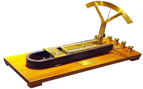
Galvanometer
The main function of a galvanometer is to convert electrical energy into mechanical energy i.e., the current supplying within the magnetic field gets changed into magnetic torque. The galvanometer device works like an actuator because it generates a rotating torque that turns aside within the reverse direction.
Construction
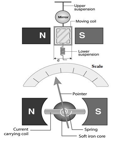
The construction of a galvanometer includes a soft iron cylinder that is enclosed through a frame wherever a coil is covered on the frame, a permanent magnet or magnet of the cylinder head is located in the region of the frame. An axial rod & pivot is located in the spindle form. A magnetic needle or indicator is mainly used to specify the readings on top of a scale. The scale readings are in ampere or A.

Construction of Galvanometer
The working of the galvanometer is, in a current-carrying coil, the current flowing is in a stable magnetic field so, the magnetic needle otherwise indicator gets turns aside to note down the measurement. The essential parts of the galvanometer include the following.
Moving Coil
In the galvanometer, the current-carrying part is a moving coil. The shape of this coil is a circular or rectangular shape. This coil includes the number of copper wire turns. The coil moves freely in the vertical axis of equilibrium in between permanent magnet poles. The iron core gives the path for less reluctance flux to provide a strong magnetic field mainly for the coil to move freely.
Suspension
The coil in the galvanometer can be balanced through a flat ribbon that holds the current and supplies to the coil. The other coil is the lower suspension where the torque effect of this is small. The material used to make a higher suspension coil is copper or gold wire in ribbon form. Here, the wire’s mechanical strength is not extremely strong, so the galvanometer can be handled cautiously without any jerks.
Mirror
The suspension holds a tiny mirror that emits the ray of light and it is placed on the scale to measure the deflection.
Torsion Head
The torsion head in the galvanometer is mainly used to control the location of the coil & for regulating the setting to zero.
Working Principle
The main function of a galvanometer is to gauge the direction, electric current & presence within the conductor. It works on the principle of energy conversion from mechanical to electrical. Once the power supply is turned ON, the flow of current within the magnetic field can be realized.
If it is open to revolve in the controlling torque, then it is turned through an angle that is proportional to the flow of current through it. This instrument is an ampere meter type, mainly used to gauge as well as to detect electric current.
Derivation
In the galvanometer, let the d & l are the lengths of individual horizontal & vertical sides of the coil within the meter.
‘N’ is the no. of turns within the coil,
‘B’ is the density of flux within the air gap like wb/m2
‘I’ is the flow of current throughout moving coil within Ampere
‘K’ is the spring constant for suspension like Nm/rad
‘θf’ is the deflection of the last steady-state moving coil within radiance
Once the current supplies throughout the coil, then it experiences a torque that is expressed as
Td = force (f) X distance (d)
The force on every face of the coil can be expressed as,
F = NBil
Therefore deflecting torque will become
Td = NBild
Td = NBAi
We know that, A = lxd
N, B & A are the constants of the galvanometer.
The constants of the galvanometer are N, B & A
Td = Gi
Where ‘G’ is the displacement constant & its value is equivalent NBA = NBld.
The controlling torque used through the suspension at ‘θF’ deflection can be expressed by
Tc = KθF
For last steady deflection Td =Tc => Gi = KθF
Thus, final deflection is θF = Gi/K
The deflection for the tiny deflection angle can be expressed like the product of the radius & the turned angle. Through the reflected ray, it can be expressed like 1000 Χ 2θF => 2000 Gi/K in mm.
The expression in the above shows that whenever the mirror turns throughout an ‘θF’ angle, then the reflected ray turns throughout a 2θF angle.
Factors
The sensitivity of a galvanometer can be effected through the following factors
- Number of spins within the coil
- Area of the coil
- Strength of the Magnetic Field
- The couple magnitude for each unit twists k/nAB
Types of Galvanometer
There are different types of galvanometers namely Tangent, Astatic, Mirror, and Ballistic. But, nowadays D’Arsonval, the moving coil or Weston type galvanometers are widely used. For an electric current detector with a moving coil, a historical name like a galvanometer is given. The galvanometer diagram is shown below.
Some more galvanometer includes the following.
- Kelvin Astatic
- Ballistic
- Horizontal
- Pouillet tangent
- Pye Coulomb Balance
- Latimer Clark Differential
- Einthoven String
- Iron Vane
- Primarily used for lectures
- Universal Tangent
- Kohlrausch
- Brass Cylindrical
- Scientology E-meter
- Mirror
- World’s largest Galvanometer at Cornell
Here the classification of galvanometers can be done by two types based on their uses like Ballistic & Dead beat/a periodic. Ballistic is mainly used to detect & measure the charge whereas periodic type is used to measure & detect the potential difference & charge within the circuit.
Based on construction, galvanometers are classified into two types like moving coil & moving magnet. Here moving coil type is again divided into two types like pivoted & suspended whereas moving magnet type is classified into two types like pivoted & suspended.
Conversions
The conversion of a galvanometer into an ammeter is discussed below.
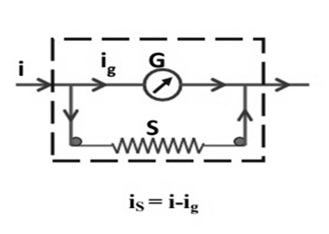
The conversion of a galvanometer to an ammeter can be done by connecting the wire with low resistance with the galvanometer in parallel. Here the potential distinction between the shunt resistance & the voltage is equivalent.

Ammeter Conversion
Vg (Voltage beyond galvanometer) = G (galvanometer resistance) X Ig (galvanometer current)
Voltage beyond shunt resistance Vs = SIs
Here, shunt resistance is ‘S’
Current beyond the shunt is ‘Is’
When the galvanometer (G) & the shunt resistance (S) are allied in potential through the circuit, then their potentials are equivalent
Is = I –Is
Vg =Vs
Gig = Sis
Gig = S (I-Is)
So, the shunt resistance (S) can be expressed as
S = Gig/(I-Is)
As compared with the current supply, the shunt current value is extremely small.
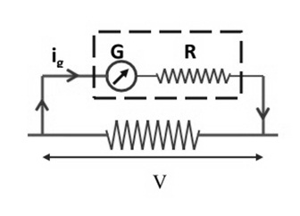
The conversion of the galvanometer into a voltmeter can be done by connecting the low resistance with the galvanometer in series.

Voltmeter Conversion
Here, the current flowing throughout the galvanometer Ig = V(voltage)/Rs (series resistance)
Rs = (V/Ig)-G
Here, the voltmeter range mainly depends on the resistance value that is allied with the circuit in series.
Difference between Galvanometer and Ammeter
Both the Galvanometer & ammeter are measuring devices but the main difference between these two devices is that the galvanometer is mainly used to compute very little current whereas the ammeter is mainly used to determine a very high current equal to 10 A.
So these two devices are the measuring devices. The implementation of the galvanometer is an ammeter that displays the precise current value which supplies throughout it. In the galvanometer, the deflection of the current can be done through a moving coil that turns among the stable magnets, and deflection of the coil takes place through the current flow.
The conversion of a galvanometer into an ammeter can be done by connecting it parallel to a resistor within the circuit. When the resistor is connected in series then it can be changed into a voltmeter. Ammeter is mainly used for determining the magnitude of current and it is also known as ampere meter as the unit of current is ampere.
Please refer to this link to know more about Galvanometer MCQs
The main difference between galvanometer and ammeter include the following.
|
Galvanometer |
Ammeter |
| A galvanometer is one kind of instrument used to detect the direction & strength of the flow of current within a circuit. | Ammeter is used to conclude the magnitude of the flowing current within the circuit. |
| It is an electromechanical device | It is a mechanical or an electric instrument. |
| Galvanometer uses a magnetic field | Ammeter works through or without a magnetic field. |
| It is less exact | It is more exact |
| It measures simply DC | It measures both DC & AC |
| It is more responsive | It is less responsive |
| The main parts of the galvanometer are the torsion head, moving coil & suspension | The main parts of the ammeter are moving coil, hot wire, moving magnet, etc |
| It is considered an actuator | Ammeter is also known as ampere meter |
| It is very useful in the measurement of bridge & potentiometer | It is very useful within the circuit. |
| It shows the flow of the current direction | It does not illustrate the flow of the current direction. |
| It is connected in series within the circuit | It is connected in series within the circuit |
| Galvanometer includes moderate resistance that ranges from 10 to 100 ohms). | An ammeter must include zero resistance. |
How to Make Simple Galvanometer at Home
Galvanometer instruments allow us to do some neat things like laser pointers, projectors, laser shows. Galvo systems are mirrors that move on a technical system to allow performers, laser lights along with music. The required components to make a DIY galvanometer include the following.
- Insulated copper wire
- Compass
- D-size Battery
- Wire Cutters/ Scissors
- Ruler/Measuring Tape
Galvanometers are mainly used for detecting electrical currents. So we can make our DIY instrument by using a copper wire, a compass, a power supply & a thin insulated wire with 3 to 4feets. At every end of the copper wire, an inch of the plastic insulation has to remove to expose bare copper wire.
- Now cover the wire approximately around the compass. Cover the copper wire strongly several times & leave 8 inches of wire at every end.
- After that, connect the bare ends of the copper wire to a cell battery & leave the circuit for 2 to 3 seconds then we can notice that the needle starts spinning. The flow of current will heat the wires & battery if we leave the circuit for few seconds.
- The flow of current throughout the circuit will generate an electromagnetic field to make the compass needle magnetized & the current supplies throughout the circuit.
- If you adjust the flow of the current direction, then you can notice a change within the direction that the needle of the compass turns.
- This DIY galvanometer is not an experimental quantify of current & it displays you the flow of current & its direction, except how many amperes are being generated.
- From other sources, we can test the current. For instance, attach two zinc or copper electrodes into half lemon piece & after that push one of the end of the galvanometer to every electrode with wires.
Advantages
The advantages of a galvanometer include the following.
- Accurate
- Reliable
- These instruments are not affected by the strong magnetic field.
- It will not change through a strong magnetic field.
- The scales of this instrument are uniform.
Disadvantages
The disadvantages of galvanometers include the following.
- Overwhelming can cause damage to the galvanometer.
- This instrument cannot be employed for the measurement of AC
- The restoring torque can be changed once the temperature is changed
- The changing of torque cannot be done easily.
Applications
The applications of the galvanometer include the following.
- These instruments are used for determining the current within the circuit
- By using this, the voltage can be determined in between two points
- This is used to determine the direction of the current supply as well as the null point.
- These are mainly used in laser engraving, laser displays, control systems, laser sintering, laser TV, etc.
- By using this instrument, controlling on the head servos status within hard drivers, DVD/CD players
- Earlier galvanometers were used in telecommunication cables to verify if there is an error, but at present, it is used in control & positioning engineering due to its accuracy & high precision.
- These are mainly used in analog to digital converters
- It is used to measure the magnitude of the device
- Galvanometers are used in the bridges & potentiometers to indicate the null deflection.
Please refer to this link to know more about Damping Ratio & Anemometer.
Thus, this is all about an overview of a galvanometer and its working. This is one kind of instrument mainly used for measuring extremely small currents within the circuit. At present, the modern type of galvanometer used is the moving coil type. When the mechanical and electromagnetic damping is eliminated from this instrument then it can be utilized like a ballistic galvanometer to gauge little capacitances & charges. Here are a few questions for you: what is the function of an ammeter? What is a Flux meter?