Force Sensor was designed by FUTEK Advanced Sensor Technology, Inc. in the USA. This is a leading manufacturing company that provides a huge variety of Force Transducers by using one of the most superior technologies within the Sensor Industry like Metal foil strain gauge technology. These transducers became the most significant element in various industrial sectors like High precision manufacturing, Automotive, Defense, Aerospace Medical, Industrial Automation, Pharmaceuticals, and Robotics wherever high precision, as well as reliable measurement, is paramount. At present, many new force measurement applications are emerging with the developments in Surgical and Collaborative Robots. So, this article discusses an overview of a force sensor – working with applications.
Force Sensor Definition
A sensor that is used to change an input mechanical load, tension, weight, pressure, or compression into an electrical output signal is called a force sensor or force transducer. This electrical signal can be changed, measured, and standardized. The force sensor symbol is shown below. The working principle of the force sensor is; when the force is applied to the force sensor then its electrical resistance will be changed.
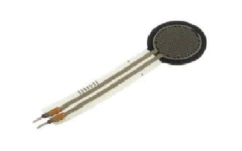
Force Sensor
Types of Force Sensors
There are different types of force sensors available in the market and each type uses different technologies to detect the magnitude of a specified force & generates an output signal. The types of force sensors mainly include Strain Gages, Load Cells & FSRs (Force Sensing Resistors).
Strain Gauges
A strain gauge is a type of force sensor where the electrical resistance of this sensor changes once force is applied. Stress is the internal resistance power that an objective will exhibit to the outside application of force whereas strain is the measure of the quantity of deformation & dislocation that the object will experience because of the applied exterior force.
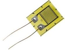
Strain Gauge
The typical strain gauge mainly includes an insulating substrate where a conductive metallic foil has been placed in a zig-zag model. Once a force is applied to the strain gauge, then the device will either elongate or compress based on the applied force direction.
The strain gauge’s compression or elongation deforms the metallic foil on the substrate to change its electrical resistance. So this electrical resistance change can be utilized to determine the applied power on the strain gauge. An electrical bridge network like the Wheatstone bridge circuit is normally used for changing the strain gauge’s resistance to a voltage measurement.
Force Sensing Resistors
The term FSR stands for “Force Sensing Resistor” which is also called force-sensitive resistor or printed force sensor. These sensors allow you to notice physical force, weight & squeezing, so these are available at less cost and are simple to use. The force-sensing resistor is designed with two layers which are separated through a spacer. Basically, force-sensing resistors change their resistive value based on how much it is pushed.
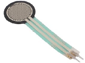
Force Sensing Resistor
Once a force is applied to the device, a conductive film is deformed & presses against a semi-conductive material printed on the substrate. When more conductive film approaches contact by the printed conductive layer, then the sensor’s resistance will be decreased. When no force is applied, then sensors will exhibit extremely high resistance. Here the applied force and resistance drops are inversely proportional.
The benefits of force sensing resistors mainly include these are thin, flexible, durable, less power consumption, and available in different sizes and styles. The main drawback lies in their accuracy & repeatability, wherever frequent measurements may differ by a minimum of 10% or above. These sensors are used to detect the change of rate for an applied force, detect touch or contact, and also to detect that an applied force has exceeded a fixed threshold.
Force Sensor Vs Load Cell
The difference between the force sensor and the load cell is discussed below.
|
Force Sensor |
Load Cell |
| A force sensor is also known as a force transducer. | A load cell is also known as a load sensor. |
| This sensor is used to measure force, compression, load & strain. | This is used to weigh/check the amount of transferred load. |
| Force sensors are classified into tensile force type, compression force type, or tensile & compression force type sensors. | Load cells are classified into different types like compression, tension, alternating & bending. |
| The calibration of this sensor should meet the non-linearity specification. | These are calibrated simply on calibration stand-by weights. |
| These are not bulky. | These are bulky. |
| These are used in different devices in the medical industry. | Load cells are used in Onboard & platform weighing, hopper scales, belt scales, weighbridge, etc. |
Force Sensor Vs Strain Sensor
The difference between the force sensor and strain sensor is discussed below.
|
Force Sensor |
Strain Sensor |
| This sensor is used for direct measurement. | This sensor is used for indirect measurement. |
| Force sensor changes their resistance once force is applied to them directly. | These are planar resistors that change their resistance in reply to surface deformation. |
| It is applicable to small forces. | It is applicable to heavy forces. |
| The best examples of these sensors are pneumatic, capacitive, hydraulic load cells, etc | The best example of a strain sensor is a strain gauge. |
Force Sensor Circuit Diagram
The force sensor circuit diagram is shown below where the type of force sensor used is FSR or force sensing resistor. Generally, the designing of switches and lighting circuits activated by sensors is very simple. So here we are going to design a force/pressure switch circuit for AC appliances. This circuit is used in Auto room lighting, theft alarms, monitoring of pressure, etc.
To design this circuit, the required components are a force sensing resistor,10K resistors -2, R3 3.6K resistor-1, Q1 2N2222 transistor, LM193IC, 1N4001 diode, 12V relay, and AC appliance. Connect the circuit as per the circuit diagram shown below. The FSR used in this circuit is normally a resistor that gives different resistance values once force/ pressure is applied to this sensor. However when no force is applied to this force sensor, then it exhibits a high resistance value. Once pressure is applied to this sensor then its resistance will drop to 100k ohms. Further, this will even drop to 100 ohms once maximum pressure is applied on the plate of a sensor.
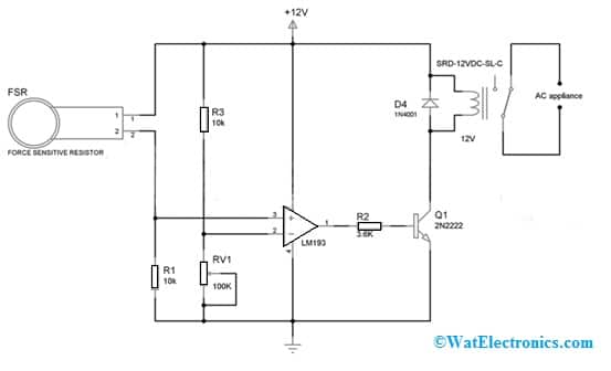
Force Sensor Circuit Diagram
Working
This circuit’s working is very simple and starts with a force-sensing resistor when the force is applied to the sensor’s plate. Here, this sensor is simply connected in series through an R1 resistor to make a voltage divider. So the output from this divider pair is given to the Non-inverting terminal of the LM193 comparator. Alternatively, the remaining voltage divider pair is simply formed with Resistors RV1 & R3 variable resistor. So the o/p voltage from this divider is given to inverting terminal of the IC. Here, the variable resistor helps in adjusting the triggering voltage or the force at which this circuit should turn on.
Whenever no force is applied to the sensor, then the output voltage from the sensor & R1 resistor pair will be low as compared to the o/p voltage of the R3 resistor & RV1 variable resistor. Similarly, whenever force is applied to the sensor then its resistance will drop so the divider pair output voltage will be increased. Now as compared to inverting terminal of the comparator, the voltage at the noninverting terminal of the comparator will be high. This o/p voltage will activate the transistor which is connected to it like a switch.
After that, a 12V relay is used to turn ON any AC appliance with 12A current rating. The output of the comparator is very low in activating the relay thus 2N2222 transistor is used to turn ON the relay. Here, the D4 diode works like a protection element for the rest of the circuit from the reverse current which supplies once the relay gets deactivated.
Force Sensor Arduino
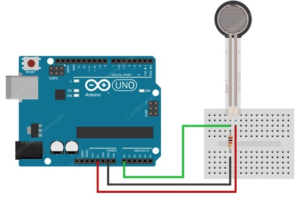
Force sensor interfacing with a microcontroller like Arduino is shown below. This interfacing gives you an overview of how the force sensor is interfaced with Arduino UNO to obtain the readings from the FSR.
The required components for this interfacing mainly include a breadboard, force sensor, Arduino UNO board, 10k ohm resistor, and connecting wires.
Connect the above components as per the following shown diagram, Here, a 10k ohm resistor is used as a pull-down resistor which is connected in series by the FSR sensor. The ADC pin of Arduino like A2 is simply connected among the pin-2 of the force sensor & 10k ohm resistor. The 5V pin of Arduino is connected to pin1 of FSR.
A force sensor includes two pins that are symmetric. So no need to differentiate these two pins. This sensor mainly changes its resistance based on how much this sensor has been pushed. If you push the sensor harder then the resistance between the two terminals will be less.
Force Sensor Arduino
Force Sensor Specifications
The specifications of the force sensor include the following.
- The actuation force is 0.2N.
- The range of Sensitivity is up to 20N.
- These are cost-effective.
- These are very thin.
- Operating temperature ranges from, -40ºC to +85ºC.
- Non-actuated resistance is 10M Ω.
- The rise time of the device is below 3 Microsecond.
- The range of bend resistance ranges from 100K to 1K Ohms based on force.
In this interfacing, the pins like A0 to A5 work like analog input pins. So, the analog input pin will change the voltage from 0 to VCC into integer values between 0 & 1023 which is known as analog value or analog value. By simply connecting the sensor’s pin to the analog i/p pin of Arduino, we can simply read the analog value with the function of analog Read() so that we can recognize how much it has been pushed.
Arduino Code
The code for FSR interfacing with Arduino Uno is given below.
int sensor_pin = A2;
int sensor_value;
void setup(void)
{
Serial.begin(9600);
}
void loop(void)
{
sensor_value = analogRead(sensor_pin);
Serial.print(“Analog reading = “);
Serial.print(sensor_value);
if (sensor_value < 10) {
Serial.println(“: No pressure”);
} else if (sensor_value < 200) {
Serial.println(“: Light touch”);
} else if (sensor_value < 500) {
Serial.println(“: Light squeeze”);
} else if (sensor_value < 800) {
Serial.println(“: Medium squeeze”);
} else {
Serial.println(“: Strong squeeze”);
}
delay(1000);
}
First, we need to define some variables like the integer variable ‘sensor_pin’ to save the ADC pin of Arduino which is connected through the force sensor. We need to define one more integer variable like ‘sensor_value’ to store the reading data obtained by the sensor.
In the setup() function at a 9600 baud rate, we will open the serial communication.
After that in the infinite loop() function, we can discover the ADC value based on the applied force on the sensor with analogRead().
Once the sensor reading value is obtained, we have to evaluate this value with set values to decide the amount of force on the sensor. The output voltage of FSR ranges from 0-5V. Here 0V indicates that less pressure is applied whereas 5V indicates the maximum pressure applied to the FSR.
Once the above code is uploaded then this will display the values of ADC which are attained by the FSR sensor when it is touched by changing force.
Advantages and Disadvantages
The advantages of force sensors include the following.
- Force sensors are available easily.
- It has very good long-term stability.
- Its accuracy is good
- Generally, it is adjusted by the vendors or manufacturers.
- Its construction is extremely thin & flexible.
- This sensor doesn’t use expensive electronics.
- These sensors can be customized, are lightweight, and use less power.
- Its accuracy level is high.
- It has outstanding linear & hysteresis behavior.
- When strain gauges are connected to the Wheatstone bridge then its temperature compensation is very good.
- There is a possibility of static and dynamic measurement of loads.
- Force sensors including force-sensing resistors give more benefits as compared to other types of force sensors like less cost, small size & good shock resistance.
- The FSR function can be simply changed by modifying the FSR properties.
- FSRs need a small interface & they can work in fairly hostile environments.
The disadvantages of force sensors include the following.
- Force sensors have less precision because their measurements vary by 10%.
- Force sensors cannot be connected to a power supply or high voltages.
- In addition, the material which is utilized to make it stretchy also loses its elasticity/flexibility because of long time twisted.
Force Sensor Applications
The applications of force sensors include the following.
- Force sensors can be used with different microcontrollers in various electronics projects. The microcontrollers are Arduino UNO, NodeMCU, Raspberry Pi, and ESP32.
- These sensors are used in scales, onboard weighing, OEM, commercial, medical and aerospace applications.
- These sensors are used in scales while weighing various materials and provide reliable results.
- These sensors are used in the medical industry for fluid monitoring, endoscopic surgery, dialysis machines, orthopedics/physical therapy equipment & MRI devices.
- Load cells are used in OEM (Original Equipment Manufacturer) applications in both low & high force environments.
- These sensors are used in aerospace applications for flap detection, force feedback, autopilot functions & data recorder in the flight.
- Force sensors are used in computer devices, consumer products, medical, musical instruments, toys, sports, automotive or industrial fields, etc.
Thus, this is all about an overview of a force sensor – working with applications. Here is a question for you, what is the piezoelectric sensor?