Flip-Flops are the basic elements of switching circuits whose main purpose is to act like an on/off switch. Based on the memory element switching has been classified as combinational or sequential. Whenever the term of the digital system rises there must be some sequence between the present and passed inputs this can only be achieved by a sequential switching circuit. The processed outputs are based on the present and the previous states in sequential but in combinational it is purely based on the present state of the given input. Based on the applications switching circuits are preferably used.
The most widely used application of the sequential switching circuit is counters. In our daily routine, we set alarms for various purposes, allotting the time limit while taking selfies etc. The applications of sequential circuits coming to digital electronics are vast enough.
This can be possible by the memory element present in the sequential circuit. The most prominent and highly used element for the purpose of storing the states is FLIP-FLOPS. These are like the foundation of the sequential circuits. Many modifications have been taken place in this field so that its versatility can be increased. Its versions updated then its transistorized version has been used in the field of computation. At present, the flip-flops made from LOGIC GATES are preferred. Even logic gates don’t have storing capabilities but still, their arrangement can make it possible by necessary modifications.
Analysis of Flip-Flops
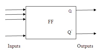
Generalized Symbol of Flip-Flops
Where Q represents normal output and Q’ represents inverted output. There can be ‘n’ inputs to a flip-flop that is responsible for the simultaneous changes in their states. These signals are known as “excitation’s”. Some flip-flops are termed as latches. The only difference aroused between a latch and a flip-flop is the clock signal. Latches are known for their non-clocked behavior.
The flip-flop because of its states is classified into four basic types:
- S-R flip-flop (set-reset)
- D flip-flop (delay)
- J-K flip-flop
- T flip-flop
(1) SET-RESET Flip-Flop
This flip-flop possesses a property of holding a state until any further signal applied. There are two inputs to the flip-flop set and reset. When the set signal is applied it sets the value of flip-flop output to 1, the outputs are switched to 0 when the reset signal is applied. If the excitation of both R and S is done simultaneously that leaves the flip-flop operation in an unpredictable manner. It is also known as a BI STABLE MULTIVIBRATOR; because of its number of stable states are two.
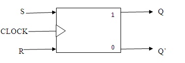
S-R Flip-Flop Block Diagram
As the s-r flip-flop is a result of cross-coupled NOR and NAND gates their excitations based on the behavior of the gates based on the applied inputs. When the inputs applied are at 0 then the change in the states left undetermined. When both are at 1 there is no chance of change in the results. The problem aroused because of NAND and NOR gates is its excitation becomes invalid. This condition to an extent is modified by using two AND gates at the input side by providing a synchronizing clock. In order to provide proper functioning one can restrict the clock pulse length and its frequency.
Block diagram
| Variations
From To |
Required input
S R |
||
| 0 | 0 | 0 | – |
| 0 | 1 | 1 | 0 |
| 1 | 0 | 0 | 1 |
| 1 | 1 | – | 0 |
Excitation table for S-R flip-flops
(2) D Flip-Flop
The output is the exact replica of the applied input value. The input passes when the value of clock is high i.e., 1 it enters the SET state, otherwise into reset or clear state.
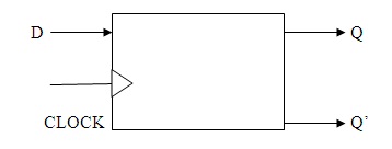
D-Flip-Flop Block Diagram
The functionality is completely based on the edge of the clock applied at the input.
| Q | D | Q’ |
| 0 | 0 | 0 |
| 0 | 1 | 1 |
| 1 | 0 | 0 |
| 1 | 1 | 1 |
Transition table of a D flip-flop
(3) J-K Flip-Flop
There is no much difference between S-R and J-K flip-flop but it has no invalid states like S-R flip-flop. It possesses the characteristics of both including S-R and Triggered flip-flops. The intermediate states in between of the J-K flip-flop are more precise compared to the S-R flip-flop.
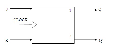
J-K Flip-Flop Block Diagram
J and K are like the set and clear inputs. In this when both J and K values are equal to 1 this combination leads the flip-flop to act like a trigger resulting it to complement state. There exists a toggle condition in J-K flip-flop.
| Changes
From |
Changes
To |
Input
J |
Input
K |
| 0 | 0 | 0 | – |
| 0 | 1 | 1 | – |
| 1 | 0 | – | 1 |
| 1 | 1 | – | 0 |
Excitation table of J-K flip-flop
Toggling condition:
When J=K=1 the flip-flop moves in the opposite state to its applied edge results in the toggle. This condition is also termed as a race around condition. This type of condition is monitored by setting the time limit of the flip-flop lesser than its propagation delay. It can be achieved by applying pulse-triggering to the flip-flops paves the way for the development of master-slave flip-flops.
(5) T Flip-Flop
It is the highly simplified version of J-K flip-flop. It consists of one controlled input value. T represents TOGGLE. When T is at the HIGH state it begins to toggle as soon as it detects the new clock signal, otherwise remains at the same state as it was previously. Like J-K we can restrict the pulse-width in this flip-flop.
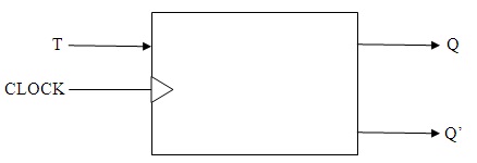
T-Flip-Flop Block Diagram
| Changes
From |
Changes
To |
Input
T |
| 0 | 0 | 0 |
| 0 | 1 | 1 |
| 1 | 1 | 0 |
| 1 | 0 | 1 |
Excitation table of T flip-flops
Check all the Questions & Answers related to Flip Flops in our detailed quiz that has 100+ Flip Flop Multiple Choice Questions.
Please refer to this link for; 74LS74 D Flip Flop.
When the input applied is at 0 then the resultant and the next state remains in the same condition. If the input is at 1 then the current and the next state will be inversely related to one another. From this, we can conclude that T is the combined value of J and k flip-flop. These T flip-flops can also be realized from the S-R flip-flops. These flip-flops are the basic elements of any digital electronic systems. Can you give any practical and the most frequently used flip-flops from the mentioned ones?