WiFi modules are also known as WLAN modules and these are electronic components utilized in various communication devices to get a wireless connection to the internet. These modules are used for transmitting & receiving data above the Wi-Fi network in the IoT field. Wi-Fi modules simply provide the connection of the internet to electronic & robotic projects. So by using these modules, one can transmit data above the internet to a robot machine otherwise make it transmit data above the internet. There are different types of WiFi modules available in the market like ESP8266, ESP12E, ESP8285, ESP8266, CYW43340/BCM43340, SSV6060P, ESP32, etc. This article provides brief information on the ESP12E WiFi module.
What is ESP12E WiFi Module?
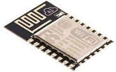
Esp-12E is a low-power consumption Wifi module mainly designed for mobile devices as well as IoT applications. This ESP12 module includes the ESP8266 SoC & other required components such as the antenna. ESP-12E module establishes a wireless network connection for the processor or microcontroller. The ESP8266EX is the core of ESP12E and it is a high-integration wireless System on Chip. This module has the capacity to implant Wi-Fi abilities to systems otherwise work like a separate application. This WiFi module is a low-cost solution, particularly for IoT applications development.

ESP12E WiFi Module
Pin Configuration:
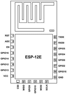
The pin configuration of the ESP12E WiFi module is shown below. This module includes 24-pin where each pin and its functionality are discussed below.

ESP12E WiFi Module Pin Configuration
- Pin1 (RST): This is a reset pin of the Wi-Fi module.
- Pin2 (ADC): It is an analog i/p pin for 10-bit ADC.
- Pin3 (EN): It is an active high enable pin of the module.
- Pin4 (GPIO16): It is a general-purpose I/O pin-16.
- Pin5 (GPIO14): It is a general-purpose I/O pin-14.
- Pin6 (GPIO12): It is a general-purpose I/O pin-12.
- Pin7 (GPIO13): It is a general-purpose I/O pin-13
- Pin8 (VDD): It is a +3.3V input power pin.
- Pin9 (CS0): This is a chip selection Pin of the SPI interface.
- Pin10 (MISO): This is a MISO Pin for the SPI interface.
- Pin11 (GPIO9): It is a general-purpose I/P Pin-9.
- Pin12 (GPIO10): It is a general-purpose I/P Pin-10
- Pin13 (MOSI): It is a MOSI pin of the SPI interface
- Pin14 (SCLK): It is a CLK Pin for the SPI interface
- Pin15 (GND): It is the ground pin of the module.
- Pin16 (GPIO15): It is a general-purpose I/O Pin-15
- Pin17 (GPIO2): It is general purpose I/O pin-2
- Pin18 (GPIO0): It is a general-purpose I/O Pin-0
- Pin19 (GPIO4): It is a general-purpose I/O Pin-4
- Pin20 (GPIO5): It is a general-purpose I/O Pin-5
- Pin21 (RXD0): It is an RXD pin of UART0.
- Pin22 (TXD0): It is a TXD pin of UART0.
Features & Specifications:
The features and specifications of the ESP12E wifi module include the following.
- Its wireless standard is IEEE 802.11 b/g/n protocol.
- Its frequency range is 2.412 to 2.484 GHz.
- It has UART, SPI & SDIO 2.0 Interface.
- It has PWM available.
- It has one ADC channel.
- Operating temperature ranges from-40ºC to +125 ºC.
- It has a programmable GPIO.
- Standby power consumption is below 1.0 mW.
- It has a PCB antenna.
- The type of wireless network is AP/ STA / STA + AP.
- Integrated low-power 32-bit MCU.
- The type of security is WPA-PSK / WEP / WPA2-PSK.
- Its leakage current is < 10uA.
- The type of encryption is WEP128/WEP64/AES/ TKIP.
- The maximum current draw for each pin is 15mA.
- The network protocol is IPv4, UDP / TCP/HTTP//FTP.
- Its operating voltage is 3.3V.
ESP12E WiFi Module Interfacing with Arduino Uno
ESP12E WiFi module which belongs to the ‘ESP-XX’ series. The series of these modules ranges from ESP-01 – ESP-15 which are based on ESP8266 SoC but they differ in flash memory, type of antenna & output pins. These WiFi modules are used by many engineers to set up and share data between two wireless communication applications. The ESP12E module is suitable for Wi-Fi communication because it has an onboard microcontroller that generates several pins. It is similar to a microcontroller including Wi-Fi in a tiny size.
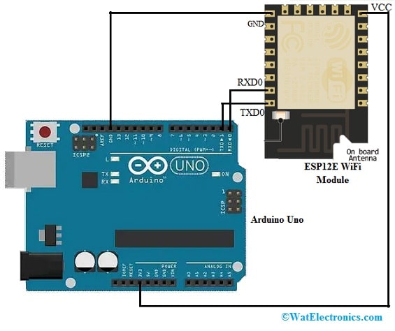
The interfacing of the ESP12E WiFi module with Arduino is shown below. The required components for this interfacing mainly include an Arduino Uno board, ESP12E module, and connecting wires. The connections of this interfacing follow as;

ESP12E WiFi Module Interfacing with Arduino Uno
- The GND pin of Arduino Uno is connected to the GND pin of the ESP12E Wi-Fi module.
- The 3v3 pin of Arduino Uno is connected to the VCC pin of the ESP12E Wi-Fi module.
- The TX pin of Arduino Uno is connected to the TXD0 pin of the ESP12E Wi-Fi module.
- The RX pin of Arduino Uno is connected to the RXD0 pin of the ESP12E Wi-Fi module.
Once the connections are made, this module is used as a WiFi access point. So this Wi-Fi module includes its name & password. By using this WiFI password, all the WiFi stations can be connected directly. The following Arduino code helps in making the ESP12E module a WiFi access point.
#include <ESP8266WiFi.h>
void setup()
{
Serial.begin(115200);
WiFi.softAP(“SSID-NAME-HERE”, “WIFI-PASS(8 MAX)”);
void loop()
{
Serial.printf(“Stations connected = %d\n”, WiFi.softAPgetStationNum());
delay(3000);
}
The library makes this WiFi mode as an access point. In the above code, WiFi.softAP is used to describe the name & password of the WiFi module.
When it is finished, the loop has a WiFi.softAPgetStationNum() to obtain the total number of connected devices details. When the device is connected then there will be an increase in the value if not it will be disconnected. Here, the wifi module acts as a hybrid with another technique that is by AT command like AT+CWMODE = 2
This command helps in making the Wi-Fi module an access point exclusive of programming. The following command is used to change the name & password of the device
AT+CWJAP=” SSID”,” PASSWORD”
The SSID must be changed by the name & password of the WiFi. Here, the Wi-Fi password must be a maximum of 8 numbers.
Similar to the above code it can also be used to interface with other microcontrollers as well. For example let’s see how it can be interface with pic-microcontroller .
ESP12E WiFi Module Interfacing with Pic Microcontroller:
#include <xc.h>
#include <stdint.h>
// Define UART Pins
#define UART_TX RC0
#define UART_RX RC1
// Define UART Baud Rate
#define BAUD_RATE 9600
void UART_Init() {
// Configure UART pins as outputs
TRISCbits.TRISC0 = 0; // TX Pin as output
TRISCbits.TRISC1 = 1; // RX Pin as input
// Configure UART for desired baud rate
uint16_t baud = (_XTAL_FREQ / (16 * BAUD_RATE)) – 1;
SPBRG = baud;
// Enable Asynchronous Serial Port
TXSTAbits.TXEN = 1; // Enable TX
TXSTAbits.SYNC = 0; // Asynchronous mode
RCSTAbits.SPEN = 1; // Enable Serial Port
}
void UART_Write(char data) {
while (!TXIF); // Wait for TX buffer to be empty
TXREG = data; // Write data to TX buffer
}
char UART_Read() {
while (!RCIF); // Wait for data to be received
return RCREG; // Return received data
}
// ESP12E WiFi Module Code
void ESP_Init() {
UART_Init();
}
void ESP_SendCommand(const char* command) {
// Send command to ESP module
for (int i = 0; command[i] != ‘\0’; i++) {
UART_Write(command[i]);
}
}
char ESP_ReceiveResponse() {
// Receive response from ESP module
return UART_Read();
}
void main() {
// Initialize ESP module
ESP_Init();
// Send AT command and receive response. The below one mentioned is a sample one. Write the respective AT command and send it // to the module.
ESP_SendCommand(“AT\r\n”);
char response = ESP_ReceiveResponse();
// Process response
while (1) {
// Main program loop
// …
}
}
In the above code the basic communication between PIC microcontroller and the ESP12E Wifi module communication is based on UART. It can also be interfaced through SPI.
The UART pins are defined as UART_TX and UART_RX, which you can modify based on your pin assignments. The UART_Init() function initializes the UART module with the specified baud rate. The UART_Write() and UART_Read() functions handle sending and receiving data over UART.
The ESP12E WiFi module functions are encapsulated within the ESP_Init(), ESP_SendCommand(), and ESP_ReceiveResponse() functions. The ESP_Init() function can be used to perform any necessary initialization of the ESP module. The ESP_SendCommand() function sends a command string to the ESP module using the UART communication. The ESP_ReceiveResponse() function reads a single character response from the ESP module.
In the main() function, you can see an example of sending the “AT\r\n” command to the ESP module using ESP_SendCommand() and receiving the response using ESP_ReceiveResponse().
AT\r\n : is the test command to check for the working of the module.
AT Command ESP12E WiFi module:
Some of the other command’s which are supported by ESP12E WiFi module are:
- AT: Test command, checks if the module is responding.
- AT+RST: Reset the module.
- AT+CWMODE: Set the WiFi mode (Station, Access Point, or both).
- AT+CWJAP: Join a WiFi network by providing the SSID and password.
- AT+CWLAP: List available WiFi networks.
- AT+CWQAP: Disconnect from the currently connected WiFi network.
- AT+CIFSR: Get the local IP address.
- AT+CIPSTART: Start a TCP or UDP connection.
- AT+CIPSEND: Send data over an active TCP or UDP connection.
- AT+CIPCLOSE: Close a TCP or UDP connection.
- AT+CIPMUX: Set the connection mode (single or multiple connections).
- AT+CIPSERVER: Configure the TCP server mode.
- AT+CIPSTO: Set the TCP server timeout.
- AT+PING: Ping a remote IP address.
- AT+GMR: Get the firmware version information.
These are just a few examples of the AT commands supported by the ESP8266/ESP-12E module. Refer to the Datasheet for more information on the other AT commands supported.
Advantages
The advantages of the ESP12E WiFi module include the following.
- This WIFI module is not expensive.
- It has very low power utilization.
- It is a small and portable Wi-Fi module.
- This module functions like a standalone application.
- It uses minimal space.
- This module includes more GPIO Pins as well as castellated edges over the PCB.
Applications
The applications of the ESP12E WiFi module include the following.
- This WiFi module is used in weather stations.
- It is used in home appliances.
- It is used in IoT-based applications.
- It is used in gaming & toy applications.
- It is used in wireless control systems.
- It is used in security ID tags & home automation.
- This Wi-Fi module is available mostly in IoT-based devices.
- This Wi-Fi module is applicable to computers, laptops, etc.
- This module is used in wireless control systems.
- ESP-12E Wi-Fi module is widely used in different home automation, networking, baby monitors, industrial wireless control, wireless positioning system signals, wireless location sensing devices, wearable electronic products & different networking applications.
Please refer to this link for ESP12E WiFi Module Datasheet.
This is an overview of the ESP12E WiFi Module – pinout, specifications, working, interfacing & its applications. Nowadays, ESP12E is the most frequently used Wi-Fi module in almost all products. These modules are available in small sizes with internal programming capability by onboard pins. This module includes a 32-bit internal microcontroller that performs various communications & o/p signals. This module is programmable in various languages. This module is available in current IoT devices to create & network hubs. ESP12E modules include all popular network protocols & safety encryption within a single IC with low power consumption & fast speed. Here is a question for you, what is Wi-Fi?