The oscillator is the foremost device in the domain of electronics and electrical applications. This crucial device is functioned to generate alternating current generally with the implementation of tuned circuits and some amplification equipment like thermionic vacuum tubes. Oscillators are specially employed to produce an increased range of frequency currents in the case of carrier waves in radio transmission probably are alleviated by linking the piezoelectric crystal (crucially quartz) with the electronic circuits. So, today this article focuses on explaining one type of oscillator circuit that is the dynatron oscillator which is invented by Albert Hull in the year 1918. Let us know the detailed explanation of the dynatron oscillator, its circuit, and its applications.
What is Dynatron Oscillator?
This is an antiquated vacuum tube type of electronic oscillator which makes use of the negative resistance feature in the early tetrode vacuum tubes, produced by the procedure termed as secondary emission. This was the initial -ve resistance kind of vacuum tube oscillator which has negative resistance features because of the secondary emission procedure taking place in the vacuum tube.
Few types of oscillators like transitron which are invented by Cleto Brunetti in the year 1939 also possess negative resistance characteristics and those are dependent on the negative transconductance. The replacement of these are dynatron oscillators which were implemented in the vacuum tube electronic devices in the period of 1970s.
The only tube that can produce dynatron oscillation is not the tetrode. Early on triodes also possess secondary emission and so has negative resistance and before the invention of tetrodes, triodes were implemented in dynatron oscillators by making the control grid more positive in nature than that of the plate. The dynatron oscillator invented by Hull, it makes use of a special dynatron vacuum tube which was designed by Hull wherein the triode a grid is a huge plate that is pierced with holes and this arrangement holds the ability to operate even in high current conditions.
Circuit Diagram
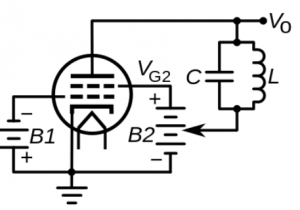
Below is the picture which shows the dynatron oscillator circuit.

Dynatron Oscillator Circuit
In a dynatron oscillator, tetrode is used. In few types of tetrodes, anode possess negative differential resistance because electrons move out of the plate when the electrons from the cathode plate knocked it which is termed as secondary emission and this generates a down kink in the plate current.
This negative characteristic is mainly observed in the older type of tubes that are used in the 1940’s period. Whereas in the current day tetrodes, in order to eliminate parasitic oscillations, the plate is covered where this diminishes the undesired secondary emissions and because of this elimination the tubes are free from negative resistance kink.
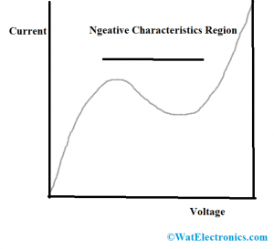
In the case of the dynatron oscillator, a vacuum tube is employed that makes use of a tetrode. And a tuned circuit is connected in between the oscillator circuit’s cathode and electrode and this arrangement stores the electric energy through the oscillations current. The tetrode exhibits negative resistance properties such as when there is an increment of electrode voltage there will be a decrement in the output current for specific frequency levels. This is termed the oscillator’s negative resistance region.
The tetrode’s negative resistance eliminates the tuned circuit’s positive resistance. So, the tuned circuit possesses null resistance and because of this resonant frequency gets generated. The necessary oscillating voltage is accomplished by selecting the necessary capacitor and inductor values for the tuned circuit. Here, the benefit of using an inductor and capacitor circuit is it can function in an extensive range of frequencies, and the oscillation frequency for the dynatron oscillator is given by
1/2∏√/LC – (R/2L + 1/2Cr)2
This is the resonant frequency of the dynatron oscillator where R, L, and C corresponds to resistor, inductor, and capacitor values, and ‘r’ represents the integer value of the negative resistance.
Dynatron oscillator Output Characteristics
The below picture shows the output characteristics of a dynatron oscillator. The device exhibits negative resistance properties so that when there is an increment in the electrode voltage, the output value decreases for a specific level of voltage so that the device functions as a detector and a normal amplifier.

Negative Characteristics
Advantages of Dynatron Oscillator
The benefits of dynatron oscillators are explained below:
- In these circuits, negative resistance is not dependent on frequency so implementing proper inductance and capacitance values in the tuned circuit allows them to employ increased frequency levels which means in the range of hertz to 20 MHz.
- As dynatron oscillators use LC tuned circuit, not including any tickler or tap coils needed by oscillators. And this advantage allows these oscillators to be used in Armstrong and Hartley circuits.
- Dynatron oscillators also possess better frequency stability when compared with LC and crystal oscillators.
Disadvantages
The limitation is that the level of secondary emission current varies from tube to tube and even it gets varied in a single tube throughout the device’s functional life and this leads to stoppage of oscillations.
Applications
The applications of the dynatron oscillator are explained below. Those are:
- Employed as detector and amplifier
- Used for measuring resistance values in the tuned circuit
- Implemented in the conversion of receivers into receivers with periodic wave code
- Used in the conversion of broadcast receivers
- In heterodyne oscillators
- Employed in beat frequency oscillators for the purpose of code reception
- Used in lab signal generators
Please refer to this link to know more about UART MCQs and Oscillators MCQs
Know more about UJT Relaxation Oscillator.
So, a dynatron oscillator is the most extensively used type of oscillator in receiver circuits and replacement for tuned circuits in the case of the superheterodyne receiver due to its extensive functional frequency range. At the time of the Second World War during 1939-1945, the usage of dynatron oscillators was in many applications. And these days, these are mostly chosen by their negative resistance characteristics in the radio receivers. It is also more important to know how the impact of temperature changes the performance of a dynatron oscillator?