The discovery of cathode-ray tubes happened in the year 19th century. In that period, the main intention of CRTs was mainly to explain and investigate the theory of the electron and this concept was known as cathode rays. And in the year 1897, a scientist named Karl Ferdinand Braun discovered the CRT oscilloscope. Whereas the invention of the dual-trace oscilloscope took place in the year 1930 by the British organization A.C. Cossor. The current day oscilloscope is the outcome of a various generation of progression those took place in the CRTs, oscillograph, analog type of oscilloscopes and digital electronics. This article is mainly focused to explain the concept of dual trace oscilloscope, its working principle, block diagram, and applications.
What is Dual Trace Oscilloscope?
Before directly knowing the dual trace oscilloscope definition, let us consider a scenario where we need to evaluate two different types of signals correspondingly. And for this, we might require two separate oscilloscopes. But it is somewhat complicated to trigger the sweep generators from the oscilloscope at a similar time period. And this complication can be reduced by implementing a dual-trace oscilloscope.
This oscilloscope is a kind of device which makes use of only one electron wave and it generates two traces, and the electron beam experiences deflection from both the separate sources. The generation of every trace has its own separate approaches where these traces are chopped. These two methods are considered to be two different approaches of dual trace oscilloscope.
Working Principle and Block Diagram
This the dual trace oscilloscope block diagram.
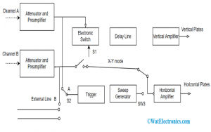
Dual Trace Oscilloscope Block Diagram
In the dual-trace oscilloscope, two different vertical input signals are displayed at the same time. The cathode ray oscilloscope is included with two similar types of vertical amplifiers having an electronic switch, a single beam CRT, and a time base generator. The output delivered from the vertical amplifiers is fed to the electronic switch through a mode managed switch. The main purpose of this oscilloscope is to produce a single electron beam whereas two traces are displayed. So, a single electron beam is utilized for the production of dual traces in order to display different signals at the same time period.
The device consists of two different input channels which are A and B. Both the channels have their own preamplifier and attenuator stages. Due to this device construction, the amplitude of every input can be controlled separately.
After the process of amplification, the two channels are fed to the electronic switch. Through a delay line, the electronic switch connects the channel to the vertical amplifier. The ‘S2’ switch, which is a trigger selector switch lets the circuit get triggered either by channel A/ channel B/ signal/ line frequency from the external source. The input to the horizontal amplifier will be from either channel B or from the time base generator via the switches ‘S3’ and ‘S1’ based on the type of operating mode.
Please refer to this link to know more about Oscilloscope MCQs
Only in the X-Y operating mode, the horizontal amplifier receives input from channel B. Other than this case, it receives from the time base generator. In the X-Y operating mode, channel B will be the input for a horizontal amplifier, and the time base generator is disconnected. And channel A functions as vertical input by plotting channel A on the Y-axis and channel B on the X-axis.
In general, dual-trace oscilloscope operates in two modes which are alternate and chopped modes.
Let us now consider the two modes of operation of dual trace oscilloscope.
Alternate Mode Dual Trace Oscilloscope Working Principle
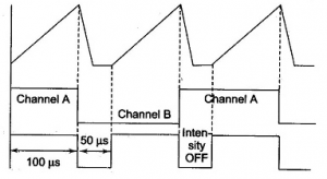
In this operating mode, channels A and B are connected using the electronic switch. Here, the channels are alternatively connected to the vertical amplifier in the successive cycle manner with the time base generator. The switching rate of the cathode ray tube is managed using the time base generator’s sweep rate. So, because of this, the CRO displays the vertical signals from the two channels one after the other. Each of these vertical amplifiers has its own standardized input alternator and position controllers in order to correctly modify the amplitude level of every signal.
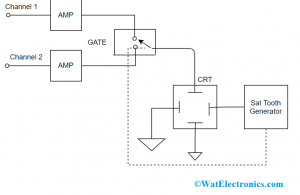
Alternate Working Mode
This alternate mode of operation is especially used for high-frequency signaling, The time base level is set up at high speed so that the traces from both the channels will be observed as continuous trace rather than the alternate trace. This is the output in the alternate mode.
Chopped Mode of Operation
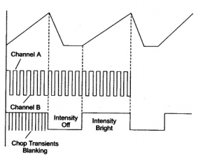
In this mode, the electronic switch undergoes multiple transitions between the two channels at the time of sweep. Here, the position of the electronic switch is regulated by using a free-running oscillator. When the switch runs at high speed, the display time of the channel is very minimal. The chopping or switching rate of the switch in this mode is nearly 0.01 milliseconds or 100kHz.
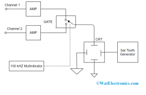
Chopped Working Mode
This chopping mode is useful mainly for synchronous observation of minimal frequency signals which means when the frequency range is minimal than that of chopping frequency levels.
This is the detailed dual trace oscilloscope working.
Working Modes
| Vertical Signal | Signal Source Triggering |
| CH1 | CH2 |
| CH2 | CH1 |
| ADD | Displays combined signal of both the channels |
| ALT | After every sweep, there happens to switch between both the channels |
| CHOP | After every sweep, there happens to switch between both the channels |
Apart from the functioning, the below section explains on few dual trace oscilloscope features. Those describe the performance and specifications of the device.
As every application in every industry has its own requirements, it is more crucial to observe the specifications and choose the desired one.
Specifications
- Deflection accuracy rate: ±5%
- Chopper frequency: Approx. kHz
- Complete acceleration voltage: 2 kV
- Operating temperature level: +5 – 400C
Performance Parameters
Bandwidth – This parameter defines the frequency level of the device that exactly measures. When the signal frequency is increased, the oscilloscope’s ability to respond gets decreased. By knowing the bandwidth level, the frequency where the displayed level value decreases to 70.7% with respect to the input sine signal is known. This point is termed as the “-3 dB” point.
Gain Accuracy – It defines the accuracy level of the vertical system that attenuates or intensifies the signal. In general, this parameter is used to know the percentage error.
Vertical Sensitivity – It states that what amount does the weak signal goes undergoes amplification. This is measured in millivolts per second. The minimal level of voltage where a general type of oscilloscope can detect is 2 mV per area of vertical display division.
Rise Time – Rise time is another approach to defining the valuable frequency level of the device. While measuring the steps and pulses, this parameter acts as the perfect performance significance.
ADC (Vertical) Resolution – This parameter when measured in bits signifies how accurately it holds the ability to transform input voltage values into digital values. The methods used for calculation augments the resolution efficiency.
Applications of Dual Trace Oscilloscope
The main applications are:
- To observe the mistakes those, arise in electro-optical systems
- Analyze the reactions of an avalanche, InGaAs, and silicon photodiodes
- Used in function generators
- Monitor a triggered event either individually or corresponding to the trigger itself.
- Assess the system performance
- Used to visualize the intensity levels of a source signal.
Know more about Digital Storage Oscilloscope MCQs & Cathode Ray Oscilloscope MCQs.
Know more about Digital Storage Oscilloscope.
Please refer to this link to know more about Dual Trace Oscilloscope MCQs
And finally, this is the concept of a dual trace oscilloscope. The article has provided clear and accurate information on Dual Trace Oscilloscope working, diagram, functioning modes, specifications, and applications. Know what are the various specifications used in various applications of dual trace oscilloscope?
