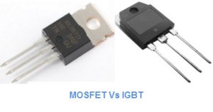
MOSFET Vs IGBT
In today’s world there are wide varieties of solid-state, switch-mode, power-supply transistors to perform switching operations in power-electronic systems. All these have their own specifications in terms of current, voltage, switching speed, load, driver circuitry and temperature. Each one has its limitations and advantages as well, but its usage depends on the requirements of the application.
In most of the switching applications Metal-Oxide Semiconductor Filed Effect Transistor (MOSFET) and Insulated Gate Bipolar Transistors (IGBTs) are predominant than the other switching devices due to their superior characteristics. These applications include Uninterruptable Power Supplies (UPS), Solar Inverters and Converters, various motor driver systems, Pulse Width Modulation (PWM) technique based applications, Switch Mode Power Supplies (SMPS), etc.
Let us see the prominent differences that make these switching devices suitable for appropriate applications. In this regard, the description of the following two switching devices is pertinent.
High-Voltage Power MOSFET
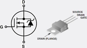
Power MOSFET
MOSFET is a most commonly used switching device, which is voltage-controlled power device unlike the BJT, which is a current controlled device. MOSFET is a low-current, low-voltage and high-frequency switching device. It consists of three terminals: gate, drain and source. It comes with two different modes: enhancement and depletion modes and the MOSFETs can be P-channel or N-channel MOSFETs. MOSFETs vary depending on the voltage level of the gate terminal.
In a depletion mode, maximum conductance takes place between the source and the drain if there is no voltage at the gate terminal, whereas a positive or negative voltage at the gate decreases the conductivity. In an enhancement mode, the MOSFET doesn’t conduct if there is no voltage at the gate terminal, and if the voltage is more, conduction takes place.
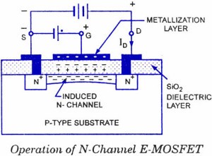
If the positive voltage is more than the threshold level applied between the gate and the source, then it creates a conduction layer by accumulating electrons. This layer is formed between the oxide layer and the P-substrate layer by pushing away the holes from the P-substrate and attracting the electrons in the N-layer. With the increase in the gate to source voltage, the size of this conduction layer increases resulting in the flow of more current from the source to the drain. In this way, MOSFET comes into conduction mode by the application of voltage across the gate and source.
MOSFET can be turned off by decreasing the gate to source voltage to below the threshold level of it. Sometimes a BJT current is required to trigger it though the MOSFET is a voltage controlled switch. It also has a body-drain diode useful in dealing with freewheeling current applications. Because its on-state resistance is low, on-state losses are also lower. MOSFETs can operate at high frequencies and low voltages and are perfectly suitable for faster switching operations with low-voltage drops. But these are restricted to be used at higher operating voltages in the range of around 500V.
IGBT (Insulated Gate Bipolar Transistor)
IGBT is designed by combining the features of both MOSFET and BJT in monolithic form. As the BJTs have high current handling capacity and MOSFET control is easy, IGBTs are preferred for medium to high-power applications. It is a minority charge carrier device and has high input impedance.
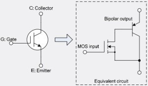
Insulated Gate Bipolar Transistor
It has three terminals: Emitter, Collector and Gate. The Gate is a control terminal, whereas the collector and emitter terminals are associated for conduction path. IGBT is a four-layer structure P-N-P-N same as that of thyristors. The below figure shows different layers of IGBT, wherein the flow of electrons through the drift region and the channel draw more holes into the drift region towards the emitter. Because the current flow is composed of the holes and electrons, the current is of bipolar nature.
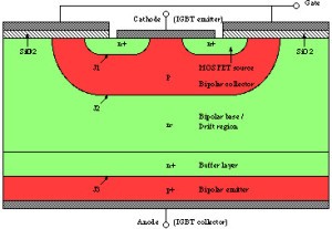
IGBT Structure
Similar to the MOSFET, when the positive gate bias is applied, it allows the inversion of P-base region under the gate and creates N-channel. During this state, the resistance of n- layer is reduced rapidly when the positive holes are injected from the p+ layer to the n- layer. This makes the IGBT to handle more currents than the MOSFET due to lower conduction losses. For turning it off – the negative bias at the gate or lowering the gate voltage to a threshold level makes it off due to no injection of holes to the N region.
Difference between Insulated Gate Bipolar Transistor (IGBTs) and High-Voltage Power MOSFETs
- MOSFET is a majority carrier device wherein the conduction is by electrons’ flow, whereas IGBT is a current flow comprising both electrons and holes. As discussed above, the injection of minority carriers (holes) to the drift region significantly reduces on-stage voltage due to conduction modulation. This is the advantage of low on-state voltage drop compared to MOSFET which is a smaller chip size and less expensive device.
- IGBT is made up of emitter, collector and gate terminals, whereas MOSFET consists of source, drain and gate terminals.
- IGBT usage is predominated for higher voltage applications as it is unipolar and requires additional freewheeling diode for the reverse flow of current. Because of this additional diode across the IGBT – it gives very high performance compared to the MOSFET.
- MOSFET and IGBT structures look very similar except for the P-substrate below the N substrate. Due to this extra layer, the conductivity is increased by the injection of holes that also reduces the on-state voltage as discussed above.
- MOSFET is rated at a voltage of about 600 volts, whereas IGBT is rated at a voltage of about1400V range. Therefore, at high voltages current becomes low eventually resulting in low switching losses.
- IGBT is preferred for low frequency (Less than 20 KHz), high voltage (more than 1000V), small or narrow load or line variations; low duty cycle, high operating temperature; and, more than 5kw output power rating applications; whereas MOSFET is preferred for wide load or line variations, low voltage (Less than 250V), large duty cycles and high frequency (more than 200KHz) applications.
- IGBT typical applications include Uninterruptable Power supplies (UPS), low-power lighting, motor control and welding applications, Switch Mode Power Supplies (SMPS), battery charging, etc., but compared to MOSFET, IGBT is predominated in several applications.
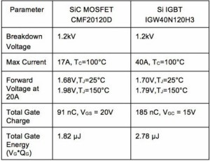
Difference between IGBT and MOSFET
In the above diagram, you can observe some comparisons of IGBT and MOSFET based on their model with ratings. Therefore, for choosing switching devices, especially IGBT and MOSFET devices there are larger parameters to be considered for the corresponding applications in power electronic field. For any application-based projects on these devices, you can contact us by commenting below.
Please refer to this for How to Select a Transistor.
Please refer to this link to know more about Freewheeling Diode & IGBT Circuit.
Photo Credits:
- Power MOSFET by nlvocables
- MOSFET Structure by circuitstoday
- Difference between IGBT and MOSFET by powersystemsdesign