A Demultiplexer is also called Demux or data distributor and its operation is quite opposite to a multiplexer because it is an inverse to the multiplexer. The multiplexer is a many-to-one circuit whereas the Demultiplexer is a one-to-many circuit. By using Demultiplexer, the transmission of data can be done through one single input to a number of output data lines.
Generally, Demultiplexers are used in decoder circuits and Boolean function generators. There are different I/O configurations De-multiplexers are available in the single ICs form. In addition, there is a cascading facility for two or above two DEMUX circuits for producing several output de-multiplexers. This article discusses an overview of a demultiplexer and its working.
What is a Demultiplexer?
A Demultiplexer (Demux) is a combinational logic circuit that includes single input and an ‘n’ number of outputs. The data which is obtained by a single input line can be transmitted to the ‘n’ number of output lines. So the function of a demultiplexer is quite opposite to a multiplexer. Multiplexers are called Data Selectors whereas Demultiplexers are Data Distributors because they transmit similar information which is obtained at the input to various outputs.
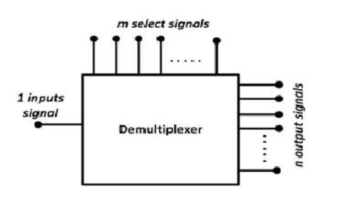
Demultiplexer or Demux
A Demux is a 1-to-n device, whereas the Mux is an n-to-1 device. The demultiplexer block diagram is shown below which includes a single input line, ’m’ select lines, and ‘n’ output lines. Here ‘m’ select lines are mainly used to generate 2m output lines. For instance, a 1-4 Demux needs 2 select lines for controlling the 4 o/p lines. In order to choose a particular output, a set of select lines need to use for controlling the specific output line which is connected to the input.
Types of Demultiplexer
There are different types of demultiplexers available depending on the different output configurations like 1 to 2, 1 to 4, 1 to 8 & 1 to 16. These Demultiplexers are available in various IC packages. Some of them are; 74139 IC is a dual 1 to 4 Demux, 74138 IC is a 1 to 8 Demux, 74237 IC is a 1 to 8 Demux including address lines, 74154 IC is a 1 to 16 Demux and 74159 IC is a 1 to 16 open collector Demux. So, the Demux ICs are also known as Decoder ICs.
- 1-to-2 Demultiplexer
- 1-to-4 Demultiplexer
- 1 to 8 Demultiplexer
- 1-to-16 Demultiplexer
1-to-2 Demultiplexer
A 1-to-2 demultiplexer (Demux) includes single input & two output lines with 1 select line. The select line signal assists to control the input to one of the 2 outputs. The block diagram of a 1-to-2 demultiplexer including an enable input is shown below.
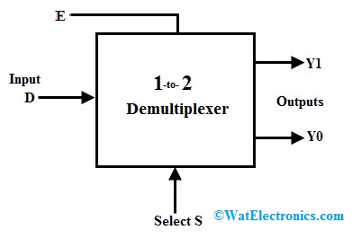
1 to 2 Demultiplexer Block Diagram
In the above diagram, the input to output lines can be connected through two methods, so a single select signal is simply sufficient to perform the operation of demultiplexing.
Once the select input is 0 or LOW, then it will be supplied to ‘X0’ & if it is 1 is HIGH or 1, then the input will be supplied to X1. The 1-to-2 demultiplexer truth table is shown below, where the input is connected to X0 & X1 based on the select input value ‘S’.
| S | D | X1 |
X0 |
|
0 |
0 | 0 | 0 |
|
0 |
1 | 0 | 1 |
| 1 | 0 | 0 |
0 |
| 1 | 1 | 1 |
0 |
For the outputs X0, X1, select input ‘S’, data input ‘D’, the Boolean expression is;
If S D = 0 1, then the expression for X0 = S’ D
If S D = 1 1, then the expression for X1 = S D
From the above 1-2 Demux truth table, the Boolean algebra Expressions can be derived but its logic diagram can be designed through 2-AND gates & 1- NOT gates. Once the select line is zero, then the primary AND gate is enabled whereas the next AND gate are disabled.
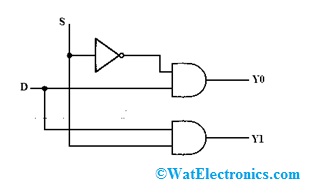
1-to-2 Demux Logic Diagram
After that, the input data can be supplied toward the o/p line ‘X0’. Likewise, once the select line is 1, then the secondary AND gate will be enabled while the primary AND gate is disabled, so data can be supplied toward the output line ‘X1’.
1-to-4 Demultiplexer
A 1-4 Demux includes a single input like D, 2-selection lines like S1 & S0 & 4 outputs like X0, X1, X2 & X3. The data at input transmits to any one of the outputs in a specified time for a specific arrangement of select lines. The 1:4 Demux block diagram and its truth table are shown below.
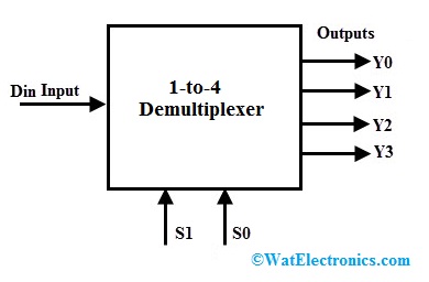
1 to 4 Demultiplexer Block Diagram
From the below truth table, we can conclude that once both the select inputs are 0 & 1, the data input can be connected to output X0. Similarly, once selection lines S0 & S1 are 0 & 1, then data input can be connected to X1 output.
|
S1 |
S0 | D | X3 | X2 | X1 |
X0 |
|
0 |
0 | 0 | 0 | 0 | 0 | 0 |
|
0 |
0 | 1 | 0 | 0 | 0 |
1 |
| 0 | 1 | 0 | 0 | 0 | 0 |
0 |
|
0 |
1 | 1 | 0 | 0 | 1 | 0 |
| 1 | 0 | 0 | 0 | 0 | 0 |
0 |
|
1 |
0 | 1 | 0 | 1 | 0 | 0 |
| 1 | 1 | 0 | 0 | 0 | 0 |
0 |
| 1 | 1 | 1 | 1 | 0 | 0 |
0 |
Likewise, the remaining outputs will be connected toward the input for the other two select lines combinations. So, the Boolean expression for the outputs can be derived by using the above truth table.
X0 = S1’ S0’ D
X1 = S1’ S0 D
X2 = S1 S0’ D
X3 = S1 S0 D
In the above expression, the input data is ‘D’, output lines are X0, X1, X2 & X3 and select lines are S0 & S1. By using the above Boolean expressions, the implementation of a 1-4 Demux can be done with 4 AND gates & 2 NOT gates.
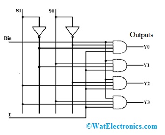
1 to 4 Demux Logic Diagram
By using the above Boolean expressions, the implementation of a 1-4 Demux can be done with 4 AND gates & 2 NOT gates. The two select lines like S0 & S1 will allow a specific AND logic gate at a time. In addition, there is a Strobe input or an Enable pin which works as a universal enable input which means when the enable bit is high then the outputs are active. So based on the combination of the select inputs, input data can be transmitted using the selected gate toward the associated output.
1 to 8 Demultiplexer
The 1-8 demultiplexer block diagram is shown below which includes one input ‘D’, 3-select inputs like S0, S1 & S2 & 8 outputs like X0, X1, X2¸ X3, X4¸ X5¸ X6 & X7. This type of Demux is also called 3-8 Demux because of the 3 select input lines & 8 output lines.
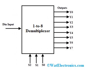
1 to 8 Demultiplexer Block Diagram
It transmits one input line toward one of the eight output lines based on the select inputs combinations like input ‘D’ is connected to one of the outputs from X0 to X7 depending on the S0, S1 & S2 select lines. The truth table of 1 to 8 Demux is shown below.
|
S2 |
S1 | S0 | Y7 | Y6 | Y5 | Y4 | Y3 | Y2 | Y1 | Y0 |
|
0 |
0 | 0 | 0 | 0 | 0 | 0 | 0 | 0 | 0 |
D |
|
0 |
0 | 1 | 0 | 0 | 0 | 0 | 0 | 0 | D | 0 |
| 0 | 1 | 0 | 0 | 0 | 0 | 0 | 0 | D | 0 |
0 |
|
0 |
1 | 1 | 0 | 0 | 0 | 0 | D | 0 | 0 | 0 |
|
1 |
0 | 0 | 0 | 0 | 0 | D | 0 | 0 | 0 |
0 |
| 1 | 0 | 1 | 0 | 0 | D | 0 | 0 | 0 | 0 |
0 |
|
1 |
1 | 0 | 0 | D | 0 | 0 | 0 | 0 | 0 |
0 |
| 1 | 1 | 1 | D | 0 | 0 | 0 | 0 | 0 | 0 |
0 |
Based on the above-mentioned truth table, for all the outputs, the Boolean expression can be written like the following
X0 = S2’ S1’ S0’ D
X1 = S2’ S1’ S0 D
X2 = S2’ S1 S0’ D
X3 = S2’ S1 S0 D
X4 = S2 S1’ S0’ D
X5 = S2 S1’ S0 D
X6 = S2 S1 S0’ D
X7 = S2 S1 S0 D
From the above Boolean equations, a 1 to 8 demultiplexer logic diagram can be designed through 8 four-input AND logic gates & 3 NOT logic gates as shown in the following logic diagram.
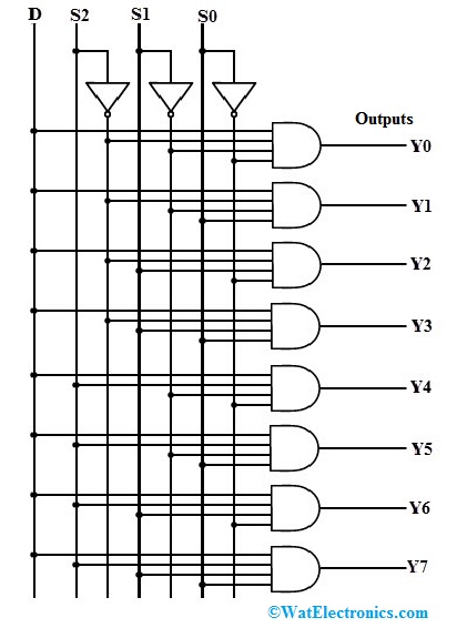
1-to-8 Demux Logic Diagram
One AND gate can be activated through different select lines combinations in a specified time so that input data will come out at the equivalent output.
Please refer to this link for Demultiplexer MCQs
1 to 16 Demultiplexer
The 1-16 demultiplexer block diagram is shown below which includes one data input bit ‘D’, four control bits S0 to S3 & 16 output bits from Xo to X15. This type of DEMUX is used to transmit a single input line to one of the output lines from X0 to X15 based on the four select lines.
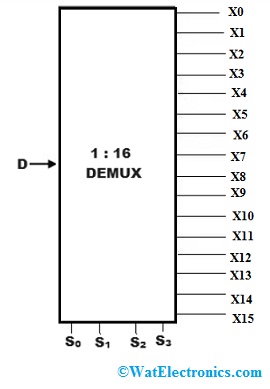
1 to 16 Demux Block Diagram
The truth table of 1 to 16 Demux is shown below.
| S3 | S2 | S1 | S0 | X15 | X14 | X13 | X12 | X11 | X10 | X9 | X8 | X7 | X6 | X5 | X4 | X3 | X2 | X1 | X0 |
|
0 |
0 | 0 | 0 | 0 | 0 | 0 | 0 | 0 | 0 | 0 | 0 | 0 | 0 | 0 | 0 | 0 | 0 | 0 | D |
|
0 |
0 | 0 | 1 | 0 | 0 | 0 | 0 | 0 | 0 | 0 | 0 | 0 | 0 | 0 | 0 | 0 | 0 | D | 0 |
| 0 | 0 | 1 | 0 | 0 | 0 | 0 | 0 | 0 | 0 | 0 | 0 | 0 | 0 | 0 | 0 | 0 | D | 0 |
0 |
|
0 |
0 | 1 | 1 | 0 | 0 | 0 | 0 | 0 | 0 | 0 | 0 | 0 | 0 | 0 | 0 | D | 0 | 0 | 0 |
| 0 | 1 | 0 | 0 | 0 | 0 | 0 | 0 | 0 | 0 | 0 | 0 | 0 | 0 | 0 | D | 0 | 0 |
0 |
0 |
|
0 |
1 | 0 | 1 | 0 | 0 | 0 | 0 | 0 | 0 | 0 | 0 | 0 | 0 | D | 0 | 0 | 0 | 0 | 0 |
| 0 | 1 | 1 | 0 | 0 | 0 | 0 | 0 | 0 | 0 | 0 | 0 | 0 | D | 0 | 0 | 0 | 0 | 0 |
0 |
|
0 |
1 | 1 | 1 | 0 | 0 | 0 | 0 | 0 | 0 | 0 | 0 | D | 0 | 0 | 0 | 0 | 0 | 0 | 0 |
| 1 | 0 | 0 | 0 | 0 | 0 | 0 | 0 | 0 | 0 | 0 | D | 0 | 0 | 0 | 0 | 0 | 0 | 0 |
0 |
|
1 |
0 | 0 | 1 | 0 | 0 | 0 | 0 | 0 | 0 | D | 0 | 0 | 0 | 0 | 0 | 0 | 0 | 0 | 0 |
| 1 | 0 | 1 | 0 | 0 | 0 | 0 | 0 | 0 | D | 0 | 0 | 0 | 0 | 0 | 0 | 0 | 0 | 0 |
0 |
|
1 |
0 | 1 | 1 | 0 | 0 | 0 | 0 | D | 0 | 0 | 0 | 0 | 0 | 0 | 0 | 0 | 0 | 0 | 0 |
| 1 | 1 | 0 | 0 | 0 | 0 | 0 | D | 0 | 0 | 0 | 0 | 0 | 0 | 0 | 0 | 0 | 0 | 0 |
0 |
|
1 |
1 | 0 | 1 | 0 | 0 | D | 0 | 0 | 0 | 0 | 0 | 0 | 0 | 0 | 0 | 0 | 0 | 0 | 0 |
| 1 | 1 | 1 | 0 | 0 | D | 0 | 0 | 0 | 0 | 0 | 0 | 0 | 0 | 0 | 0 | 0 | 0 | 0 |
0 |
|
1 |
1 | 1 | 1 | D | 0 | 0 | 0 | 0 | 0 | 0 | 0 | 0 | 0 | 0 | 0 | 0 | 0 | 0 |
0 |
From the above tabular form, the Boolean expressions can be formed like the following.
X0= S0′.S1′.S2′.S3′ D
X1= S0′.S1′.S2′.S3 D
X2=.S0′.S1′.S2.S3′ D
X3= S0′.S1′.S2.S3 D
X4= S0′.S1.S2′.S3′ D
X5= S0′.S1.S2′.S3 D
X6= S0′.S1.S2.S3′ D
X7= S0′.S1.S2.S3 D
X8 = S0.S1′.S2′.S3′ D
X9 = S0.S1′.S2′.S3
X10 = S0.S1′.S2.S3′ D
X11= S0.S1′.S2.S3 D
X12 = S0.S1.S2′.S3′ D
X13= S0.S1.S2′.S3 D
X14= S0.S1.S2.S3′ D
X15= S0.S1.S2′.S3 D
From the above Boolean equations, a 1 to 16 demultiplexer logic diagram can be designed through 16 AND logic gates & 4 NOT logic gates as shown in the following logic diagram. Here, one AND logic gate can be enabled through various select lines combinations within a particular time so that input data will appear at the output.
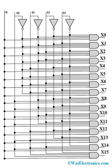
1 to 16 Demultiplexer Logic Diagram
Which IC Works as a Demultiplexer?
There are different Demultiplexer ICs available like 1-4 Demux is 74139 IC, 1-to-8 demultiplexers are 74237 IC, 74138 IC, 1-16 Demux is 74154 IC, 4-16 line Decoder IC like 74159.
Advantages & Disadvantages
The advantages of Demultiplexer include the following.
- The efficiency of the communication system can be improved with the help of the Multiplexer & Demultiplexer combination
- A demultiplexer separates back the mutual signals into streams.
- Its function is quite opposite to multiplexer
- It can be used as a decoder in the security systems
- The combination of Mux & Demux is used for the transmission of Audio or Video signals.
The disadvantages of demultiplexer include the following.
- Bandwidth wastage can be occured
- Delays can be occurred due to the synchronization of the signal
Where is Demultiplexer Used?
The applications of Demultiplexer include the following.
- Demultiplexers are used in control systems, microprocessors to enable or select a single signal from a number of signals
- Demux is used to choose several IO devices’ data routing.
- Selecting different banks for memory decoding.
- Implementation of a Boolean function
- To enable various functional units
- Used in synchronous systems for data transmission
- Data acquisition systems
- It enables several rows in memory chips based on the address
- Designing of combinational circuits
- Monitoring systems for security
- Automatic test equipment systems
- Demultiplexers are used within CLK data recovery solutions.
- Applicable in wavelength routers.
- Used in the communication system for transmission of data
- Used like a serial to parallel converter.
- These are used in the broadcasting of ATM packets
- The ALU output is stored within particular registers with the help of Demux
Please refer to this link to know more about Multiplexer MCQs.
Thus, this is all about an overview of Demultiplexer, types, and their applications. A demux or demultiplexer or a data distributor is a circuit, used to transmit several outputs using a single input. So this circuit performs a single input through multiple output switches. Here is a question for you, what are the characteristics of a Demultiplexer?