Damping of the oscillatory system is the effect of preventing or restraining or reducing its oscillations gradually with time. The damping ratio in physical systems is produced by the dissipation of stored energy in the oscillation. It is the restraining or decaying of vibratory motions like mechanical oscillations, noise, and alternating currents in electrical and electronic systems by dissipating energy. Examples of damping are; viscous drag in mechanical systems, resistance in electronic oscillators, absorption of light in optical oscillators, shock absorbers in automobile systems, suspension of mass from spring.
It is also important in other oscillating systems like biological systems and bikes. The level of damping of the system is divided into 4 types. They are undamped, underdamped, critically damped, and overdamped. To know the number of oscillations decayed with time, the damping ratio is to be calculated. This article explains the damping ratio of a control system / second-order system / closed-loop system and its significance.
What is Damping Ratio?
Definition: The damping ratio is defined as the number of oscillations in a system that can decay or restrain after an interruption and it is a dimensionless measurement. Most of the systems work in oscillatory mode when they are interrupted or disturbed from their initial position. For example, suspension of mass from a spring. If the mass is pulled and released, then it bounces up and down. The system tries to return to its initial static position after every bounce.
The movement of the mass is resisted due to the damping and the spring. After some time, the frictional losses damps the system and the oscillations would decay gradually by reducing or attenuating the amplitude. Therefore, this is referred to as the number of oscillations decayed by the system rapidly from one bounce to another.
The damping ratio symbol is denoted as ‘ζ’ (Zeta).

Damping of Harmonic Oscillator
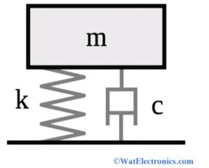
The damping ratio gives the level of damping in the control system related to critical damping. Consider a damped harmonic oscillator with mass m, spring constant ‘k’, and damping coefficient C as shown in the figure below. Then the damping ratio is defined as the ratio of actual damping to the critical damping of the system. It is the ratio of the damping coefficient of a differential equation of a system to the damping coefficient of critical damping.
ζ = C/Cc
ζ = actual damping / critical damping
The differential equation of motion of a system is written as,
m d^2x/dt^2 + c dx/dt + kx = 0
The critical damping coefficient formula is given as
Cc = 2 √km (or) Cc = 2m √(k/m) = 2mωn
Where ωn = √(k/m) = natural frequency of the system. For example, the frequency of the vibrating tuning fork.
The ratio of two coefficients of identical systems gives the damping ratio, which is a dimensionless measurement. It expresses the level of damping of the system mathematically.
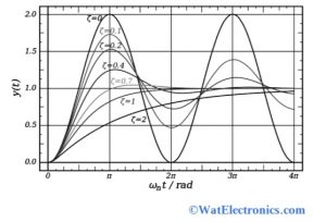
The damping ratio of the control system varies from underdamped (ζ<1), overdamped (ζ>1) critically damped (ζ=1) and undamped (ζ=0)
The effect of variation in the second-order system is shown in the below figure.

Damping of Sinusoidal Waveform
The general exponential damping equation of a sinusoidal signal is given as,
y(t) = A. e-λt.cos(ωt-Φ)
Where y(t) is the instantaneous amplitude of the signal at time t.
‘A’ is the amplitude
‘λ’ is the decay rate of the signal
‘Φ’ is the phase angle at time t=0
‘ω’ is the angular frequency.
Formula
The damping ratio formula for the closed-loop system is discussed below.
The formula in the control system is given as,
ζ = actual damping / critical damping
ζ = C/Cc = C/2√mk
To derive the damping ratio in the control system or damping ratio in a closed-loop system, consider the differential equation of the second-order system, which is given as,
(d^2x / dt^2) + (2ζωn dx/dt) + (ωn^2x) =0
Where ωn = √k/m is the natural frequency of the system.
The above equation is more general than mass-spring action systems and applicable to electrical circuits and other systems.
The damping ratio in the control system can be solved with another approach. That is,
X(t) = Ce^xt
Where ‘C’ and ‘s’ = complex constants
And s = -ωn(ζ + i√(1-ζ^2)) or
s=-ωn(ζ + i√(1-ζ^2))
Therefore the two values of s and damping ratio combine to obtain a general real equation that helps to understand the decaying properties of the system.
Consider the following cases to understand the level of damping of the control system
- When ζ = 0, the system is undamped and the expected solution would look like exp(i.ωn.t)
- When 0 < ζ < 1, then the system is said to be underdamped, where the complex exponential decaying solution of an oscillatory system looks like exp(i.ωn√(1-ζ^2.t)
- When ζ > 1, the system is said to be overdamped. Where the value of s is real and the result is the sum of two decaying exponentials and no oscillation occurs.
- When ζ = 1, the system is said to be critically damped. In this case, obtaining the desired solution requires a damped oscillator.
Hence from the above conditions, we conclude that this is a non-dimensional measure of a control system or second-order control system with a decay rate related to the natural frequency.
ζ = λ / ω (or) ζ = λ / √(λ^2 + ω^2) < 1
The relation between the ‘Q’ factor, damping ratio, and decay rate of the system is given as
ζ = 1/ 2Q = α / ωn
Where Q factor is also a non-dimensional measure of the damping of the system. If the value of Q is high, then the system exhibits slow damping corresponding to the oscillation.
‘α’ represents the decay rate parameter.
How to Find the Damping Ratio of a Second-order System
As we know, the response of high order systems is obtained from the first order and second-order systems. Since the responses of second-order systems are more difficult to understand than first-order systems and require extra time to solve the issue.
To find the damping ratio of a second-order system, consider a closed-loop system with the differential equation as given below,
(d^2y / dt^2) + (2 ζωn dy/dt) + (ωn^2y) = ωn^2x
Now by applying the Laplace transform both sides with initial conditions, we get the input and output transfer function as,
Y(s) =[ ωn^2 / (s^2 + 2 ζωn + ωn^2) ] X(s)
This is the differential equation for a second-order system with poles and no zeros.
Since the poles of the second-order system are located at,
S = -ζωn + ωn √(1-ζ^2) and
S = -ζωn – ωn √(1-ζ^2)
The response of the second-order system is known from the poles. Because all the information about the damping ratio and natural frequency is encoded by the poles.
The time constant with exponential decay is given as
1/α = 1/ζωn
The damped natural frequency is written as
ωd = ωn √(1-ζ^2)
The damped natural frequency is similar to the natural frequency and also equal to the frequency of the decaying sinusoidal waveform (underdamped)
Hence,
s = -α + jωd and s = -α – jωd
Where ‘ωn’ is the natural frequency of the underdamped system
‘ζ’ is pronounced as zeta, which is a damping ratio symbol.
Consider the following conditions to know whether the control system is overdamped or underdamped or critically damped.
Case 1: When ζ>1, both poles are real and negative. Then the system is said to be overdamped.
Case 2: When ζ = 1, both poles are equal, real and negative. Hence the system is damped critically. Since s = -ωn
Case 3: For 0 < ζ < 1, the poles are negative real with complex conjugates. In this case, the control system is said to be underdamped.
S = -ζωn +- ωn √(1-ζ^2)
Case 4: The poles are imaginary and complex conjugates at ζ = 1. Here s= +/-jωn. Therefore the system is considered undamped.
Case 5: The system is considered unstable only when ζ < 0. Both poles are located at the right half of the Laplace plane.
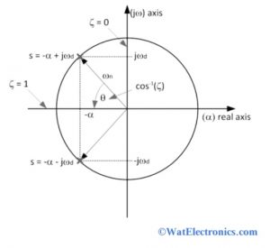
The graphical representation of damping frequency and damping ratio ζ is shown below.

Graphical Representation
- From the above figure, the frequency of the oscillations in the response of the system is represented on the pole vertically
- The reciprocal of time constant with exponential decay is represented on the horizontal pole.
- If the pole is located to the left side of the s-plane, then the faster transient response starts diminishing.
- The underdamped natural frequency ωn is the distance between the pole and the origin of the s-plane.
- It can be given as ζ = cosθ. Where θ represents the angle of the pole on the horizontal axis.
Significance
The significance of the damping ratio includes the following.
- It is used to determine the level of damping of the system.
- It helps to know whether the system indicates undamped or underdamped or critically damped or overdamped.
- The natural frequency response of a second-order control system can be determined from the damping ratio.
- It is important in the harmonic oscillator to determine the decay rate of the oscillations with respect to time.
- The exponential decaying of oscillations of the system is measured.
- When the system is critically damped, the vibration is prevented to allow the system to return to its static equilibrium position with a short period.
The percentage overshoot (PO) can be calculated with the damping ratio ζ
PO = 100 exp (-ζπ/√(1-ζ^2))
The percentage overshoot is the output value that exceeds the final steady-state value.
The produced damping ratio with the given PO (percentage overshoot) can be calculated with the below formula.
ζ = [-ln(PO/100) / √(π^2 + ln^2 (PO/100)) ]
The oscillatory behavior of the system depends on the damping ratio.
Please refer to this link to know more about Synchroscope.
Please check this article to know more about Damping Ratio MCQs
Thus, this is all about an overview of damping ratio, damping ratio formula in the control system, symbol, working in the control system, closed-loop system, the second-order system, derivation in control system & its significance. Here is a question for you, “What is the advantage of damping in a control system? “.