A diode is a semiconductor device through which current supplies in one direction only. The initial diodes were crystal diodes which are used as rectifiers in radio kits. In this diode, a weak signal was fed into the crystal material using a very fine wire namely the cat’s whisker.
The crystal material in the diode removes the high-frequency carrier signal of radio by allowing the elements of the signal through the audio data to approach through clear. The crystal material was packed with impurities so that some sections will become more resistant to the flow of current. This article discusses an overview of a crystal diode.
What is a Crystal Diode?
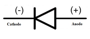
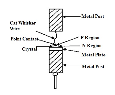
A crystal diode is also called a Cat’s whisker because it is a type of point-contact diode. This diode operation mainly depends on the contact’s force among the point & semiconductor crystal. This diode includes a metal wire that is pressed next to the semiconductor crystal. Here, the crystal acts works like a cathode & metal wire acts as an anode. These types of diodes are outdated within nature and used in detectors, microwave receivers, and rectifiers. The crystal diode symbol is shown below.

Crystal Diode Symbol
Here, crystals are more popular semiconductors, so semiconductor materials are frequently known as crystals. This is how crystal triodes & diodes are named. These diodes are available in different types like common diodes which are mainly used for switching, rectifying, detecting, etc, and diodes including particular properties like voltage stabilizing, LEDs, photosensitive, etc.
Crystal Diode Construction
A crystal diode is designed with two dissimilar kinds of semiconductor materials beside the other. In this diode, one side is simple to flow the electrons whereas another side is not easy. But electrons try to jump from one side to the other across the border to form a current and nothing will take place. The alternating current which comes from outside can change by the diode to the direct current that most appliances require.

Crystal Diode Construction
Generally, these diodes are also called point contact diodes which are the old type microwave semiconductor devices. These were mainly designed for utilizing in microwave receivers & at present, they are still used like detectors & receiver mixers. As compared to PN junction diode, crystal diodes mainly depend on the contact force among a semiconductor crystal & the point for its action.
Throughout this diode manufacturing, the huge current is supplied from the cat whisker to the Si crystal. The outcome of this huge current will form a small p-type material region in the region of the crystal within the surrounding area of the point contact so that a PN junction can be formed.
Crystal Diode Application
The electric power which is obtained from outside is mainly used for transmission that is AC; however, most of the devices work by using DC supply. As a result, we need to change AC to DC by using a rectifier circuit. Most of the rectifiers employ this diode through some resistors which are called crystal diode rectifiers. These are divided into two types like HWR 0r half-wave rectifier and FWR or full-wave rectifier.
The half-wave rectifier (HWR) conducts current simply in the positive half cycle of the applied input voltage. In this rectifier, the AC supplies negative half cycles are suppressed. As a result, no current will be conducted & no voltage shows beyond the electric load. So flow current always in one direction throughout the load.
In a full-wave rectifier (FWR), the flow of current throughout the load will be in the same direction for both the semi cycles of input AC voltage supply.
Crystal Diode Characteristics
The core of the crystal diode is the PN-junction and the main characteristic of this diode is unidirectional conductivity. The crystal diode’s conductivity can be determined through the applied voltage across the diode & the flow of current throughout the diode. The main relationship between these two is known as the VI characteristics of the crystal diode. This diode characteristic can be divided into two main parts namely forward characteristics & reverse characteristics.
Forward Characteristic
Once the forward voltage is applied across the diode then it increases gradually from zero. In the beginning, the forward current is approximately zero & this diode gives a high resistance which is known as the dead zone. The dead zone voltage of the Si diode is 0.5V and the dead zone voltage of the Ge diode is 0.2V.
When the diode’s forward bias voltage is low as compared to the dead-band voltage; its forward current is zero. Once the applied voltage surpasses the dead-band voltage, the forward current starts to come into view until it is equivalent to the on-voltage & the forward current raises quickly. At this moment, the diode will be in the forward conduction position. The Sil tube’s conduction voltage is 0.6 – 0. 7V and for the germanium tube is 0.2 to 0.3V.
Reverse Characteristics
Whenever the reverse voltage is applied to the diode, the reverse current can be formed which is very small, and it does not change with the change of the reverse voltage within a large range. So this area is known as the reverse cut-off region.
The current that supplies once the reverse cut-off is known as reverse saturation current. Generally, silicon tubes include minimum microamperes to hundred microamperes whereas germanium tubes include a hundred microamperes to thousands of microamperes.
This current is a significant parameter to gauge the diode quality. When the value is small then the quality of the diode is better. Generally, the reverse saturation current can be ignored & in the reverse direction, the diode is considered non-conducting.
If the reverse voltage increases continuously to a fixed value, then the reverse current will increase suddenly. This incident is known as a reverse breakdown. At the moment, the applied voltage beyond the diode is known as the reverse breakdown voltage. This fact is not allowed once ordinary diodes are usually used. The diode is activated through a fixed forward voltage & reverse voltage cut-off characteristic which is known as unidirectional conductivity.
Please refer to this link for Choosing resistor values for diodes.
Advantages
The advantages of crystal diode include the following.
- These are more rugged, smaller
- Longer life
- Cheaper & Simpler
- They need no filament power. Consequently, they generate less heat as compared to the equivalent vacuum diodes.
Disadvantages
The disadvantages of crystal diode include the following.
- These are very heat sensitive
- As compared to vacuum diodes, they can handle low inverse voltages and small currents.
- They cannot place an overload even for a small phase
Please refer to this link to know more about Rectifier diode and Laser diode.
Thus, this is all about an overview of crystal diode circuits using a half-wave rectifier, working, characteristics, advantages, and disadvantages. Here is a question for you, what are the applications of crystal diode?