Coupling capacitor is the basic type of capacitors. A capacitor is a storage device that is known for storing the charge. Its structure is very simple in design. Parallel plates that are present in a capacitor are separated by the dielectric. Hence this makes the capacitor capable to store charges. A capacitor is available in various forms. One of the forms of this capacitor is coupling capacitors.
The purpose of this type of capacitors is that to couple the output of the signal in AC form to the other circuit as input. Because the capacitor is known for its property of blocking DC signals. Hence these types of capacitors are useful when the circuit desires of the AC signals. The best suitable example will be the microphone because in this the circuit elements are powered ON because of DC. But the input and the output signals are both of the form of speech that is AC signals.
What is a Coupling Capacitor?
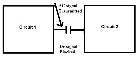
A capacitor that couples the output AC signal generated in one circuit to another circuit as input is defined as the coupling capacitor. In this case, the capacitor blocks the entering of signal that is DC into the other circuit from the previous circuit. These are the widely used in the audio circuits and mostly preferable where the concern is about AC signals.
Construction:
The coupling capacitor is a general parallel plate capacitor. Its construction is very simple. Just a dielectric is present in between the parallel plate capacitors. This coupling capacitor is good at obtaining final output as AC signals. There exist decoupling capacitors as well in which the output generated is consisting of DC signals. Hence coupling capacitors are preferred in analog circuits. In the case of decoupling capacitors, these are preferred in digital circuits.

Coupling capacitor General Representation
Coupling Capacitor Working
The coupling capacitor, generally only allows the AC signal to be transmitted from one circuit to another. Let us see how it happens. AC signal is sinusoidal it has both negative and positive cycle whereas a DC signal is just a straight signal. When a DC signal is applied to the capacitor, it just charges and once the capacitor is full charge there will not be any flow of current. Whereas when a AC signal is applied during the positive cycle of the signal the capacitor charges as ususal but when negative cycle is applied the holes and electrons starts moving in the opposite direction as a result the capacitor discharges and so there is a continous flow of current. This capacitor is proven to be very advantageous in various fields. These kinds of coupling capacitors are present in the circuits that are preferably known for its audio transmission. These are connected in a series concerning the load.
Coupling Capacitor Calculation
The capacitance of the coupling capacitor can be calculated similarly to that of the basic capacitor. Capacitance is measured in terms of the unit known as Farads. But the farad is the largest unit so it is divided into sub-units of picofarads, micro farads, and nano farads
C=1/2*3.14*f*X c
The above equation gives the value of minim capacitance required for AC coupling.
Applications:
There are various coupling capacitors applications. Some of them are listed below.
-
Substation
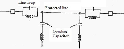
In the purpose of the communication of the power line, the coupling capacitors are preferred. After the trap of wave, these are placed. It ranges from 2200 pf to 10,000 pf. If the circuit possesses high-frequency signals then the capacitor functions in such a way that it offers low impedance value and vice-versa.
-
Voltage Transformer
The voltage transformers that are connected along with the transformers in such a way that the values of the voltages converted into measuring values which are derived from the high transmission lines. This type of circuit is known as switch gear.
The Capacitor Voltage Transformers (CVT) is used in the voltmeters, tariff meters, and relay circuits designed for protection… Generally, a voltage transformer purpose is to step down the values of the voltages to design a protecting circuit with the help of relays.
-
PLCC
PLCC is power line communication control equipment. The design of this PLCC is to make use of it in telecontrol and telemetry. The PLCC design mainly consists of a coupling capacitor as basic equipment of PLCC.

Coupling Capacitor PLCC
The carrier equipment and the respective transmission line are coupled via the coupling capacitor. It allows the carrier frequency to enter into the respective carrier equipment. It offers the value of impedance low to the carrier frequency and the high impedance for the respective power frequency.
- BJT
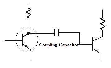
In BJT, it is utilized in the circuits of amplification it requires multiple-stage involvement for this purpose. During multiple stages, a capacitor is connected between the two stages. So that output of one stage can be coupled as the input to the next stage. In this coupling capacitors are utilized in the BJT’s.

Coupling Capacitor in BJT
From the above description it can be known that the coupling capacitor is mostly part and parcel of any circuit and. Can you calculate how much capacitance should be preferred in substations?
Please refer to this link to know more about Film Capacitor.