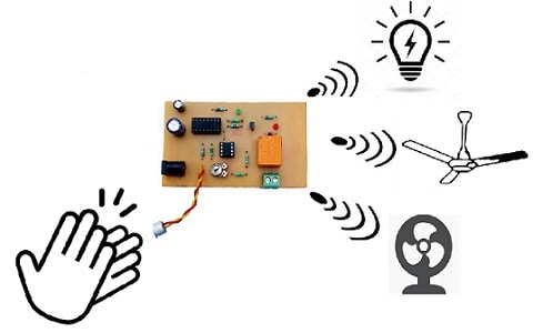
As the name suggests, clap switch is a simple interesting project for beginners and hobbyists. This circuit is used to make the light ON through a clap sound but it can work through any kind of same pitch sound. The essential components used to build this project are electric condenser mic as a sound sensor. The main function of this device is to change the energy of sound to electrical.
A 555 timer through a transistor activates the LED and after some time, it will be turned OFF. When this circuit is connected to any electrical load, then it turns ON & OFF only through clap sound. This simple project is very useful as it doesn’t need any exterior mechanism to perform the particular operations. This article discusses how to make a clap switch using 555 timer IC and its working.
What is a Clap Switch?
A circuited which operates through clap sound otherwise similar to that sound is called clap switch. This switch activates once or twice clapped & deactivates when again clapped once based on the design of the circuit.

Clap Switch Working
The fundamental concept of the clap switch is that the microphone used in this circuit receives the clap sound & generates a small signal to controls a lamp. Generally, this switch is operated through sound. For instance, light, fan, TV can be controlled through clapping.
Block Diagram
The working of the clap switch is discussed through the block diagram of the clap switch. This block diagram includes an audio amplifier, bistable flip flop & circuit amplifier. In the above block diagram, an audio power amplifier is used to amplify audio signals with less power to a level appropriate for controlling loudspeakers.
A flip-flop is a circuit that includes two stable conditions which are used to store state data, so it is described as sequential logic. The flip flop is a bistable multivibrator and used as data storage elements.
When employed in a finite-state machine (FSM), the next state & output mainly depend on its present input as well as the current state. So it can be used for pulse counting and also for coordinating input signals which are variably timed to some timing signal.
A bistable circuit includes two stable states wherever the output of this can be either logic 0 or 1 based on the received signals at the inputs. The simple bistable circuit includes two NAND gates.
Clap Switch Circuit Diagram
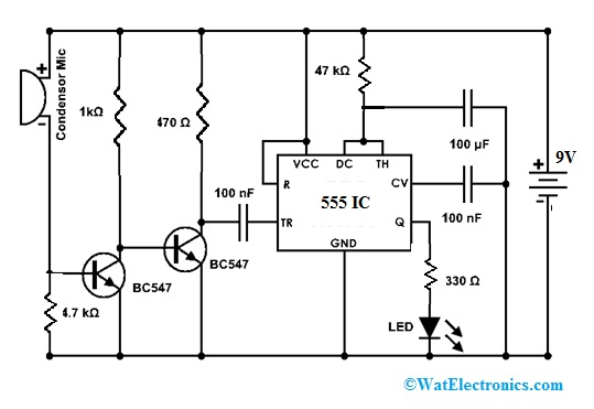
The circuit diagram of the clap switch using 555 timers IC is shown below. Here, a 555 timer is an essential component used in this circuit. Before going to know this circuit, we have to know what is 555 timer and its function in this circuit.

Clap Switch Circuit using 555 IC
As the name suggests, there are mainly three 5kΩ resistors that are connected internally to produce the reference voltage of two comparators. This IC is a very popular, low cost & helpful exact timing device that can perform like either a timer to produce single pulses otherwise long time delays to generate a stabilized string waveforms by changing the duty cycles from 50-100%.
This is an extremely strong & stable IC with 8-pins. The operation of this IC can be done in three modes like Asrable, Bistable & Monostable to generate different applications like delay timers, one-shot, LED, pulse generation, lamp flashers, tone generation, alarms, logic clocks, power supplies, converters, frequency division, etc.
Required Components
The clap switch circuit using a 555 timer can be built with different electronic components which include the following.
- Resistors like 1k, 47k, 4.7k, 470 ohms & 330 ohms
- Battery – 9V
- Capacitors – 10mF capacitors -2 & 10µF
- 555 Timer
- Condenser Mic
- LED
- BC547 transistors – 2
Working Principle of Clap Switch Circuit
This circuit uses a sound-activated sensor as an input to detect the clap sound & generates the output by processing the input into the circuit. Once clap sound is provided to the Mic, then it gets Electrical Energy & turns ON LED. After some time, automatically the LED will be turned OFF. By changing the 100mF capacitor value, the activated LED timer can be modified because it is connected through a 555 timer. The main function of this is to generate a signal.
The input of this circuit is clap or even any sound having the same pitch of clap sound. So this is also called a sound-activated switch. This circuit mainly uses transistors as the negative terminal of electric Mic is connected directly through the transistor. This circuit doesn’t use any kind of switch to control the circuit.
Once the battery is connected to the circuit then the circuit will be activated. This circuit takes the input from the clap in the sound energy form. This circuit can be changed by employing a relay-like switch to control the circuit. Once the sound input is given to the circuit by clapping, then the sound signals can be changed to process them to the IC that generates the signal toward the light-emitting diode to activate the LED.
In the above circuit, you have to make sure if the negative terminal of the Condenser Mic is connected through the amplifier, then the circuit will heat up & may not work through different transistors models, etc. This circuit can also be used for different loads like fans, LAMP & other appliances. So there are many chances to adjust this circuit.
Advantages
The advantages of the clap switch circuit include the following.
- The main benefit of clap switch is, we can control any electric load like light, a fan from any place in the room by clapping our hands.
- Energy-Efficient System
- Less Cost
- Circuit is Reliable
- High Accuracy
- Man Power is not Required
Disadvantages
The disadvantages of the clap switch circuit include the following.
- The main drawback is that it is usually awkward to have to clap one’s hands to control the load
- It normally looks simple in most cases to utilize a normal light switch.
- Unnecessary disturbances may occur while operating in buildings.
Applications
The applications of clap switch circuits include the following.
- A clap switch is used to switch ON/OFF different electrical appliances like the following.
- Fan
- Light
- TV
- Motor
- AC
- This system is very useful for mobility-impaired persons and elders
Please refer to this link to know more about 555 IC Timer MCQs.
Thus, this is all about an overview of clap switch and its working with advantages, disadvantages, and applications. In the future, this circuit can be enhanced by enhancing the equipment range using a better Mic. So this can be utilized as a remote controller. Here is a question for you, what are the different ICs used to make a clamp circuit?