During the process of rectification, the output generated will not result in the pure DC form. Instead, there is the presence of ripples in the output. The ripples are the unwanted AC part present in the output DC. This affects the efficiency of the circuit. The frequencies that are undesirable to the circuit can be filtered by connecting the capacitor filter across the load. As we use voltage regulators these capacitor filters are kept after it so that the output that is generated gets smoothened. Hence it is proved n to be more advantageous to the half and full-wave rectifier circuit.
What is Capacitor Filter?
Capacitors that connected across the load in order to filter the generated output are known as the capacitor filter. Generally, a load resistor is present in both the half and full-wave circuits in order to remove the ripples from the output DC this filter is placed along with the load. This is the main intention of introducing capacitor filters in the rectifiers.
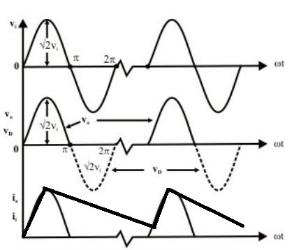
As excited voltage flows through the connection terminals of the capacitor it gets charged enough and the current is supplied to the load. The capacitor tends to charge enough until reaches the maximum value of the applied input wave. Once the maximum is reached then the voltage of the rectifier slowly gets degraded as well as the capacitor gets discharged.
The degradation in the wave occurred is not complete it will just come down but the continuity is present because the next peak occurs simultaneously. Hence this phenomenon is in continuation and the output generated if there are any ripples in it the filter connected to it just removes it in order to make it smooth.
Analyzing Half Wave Rectifier
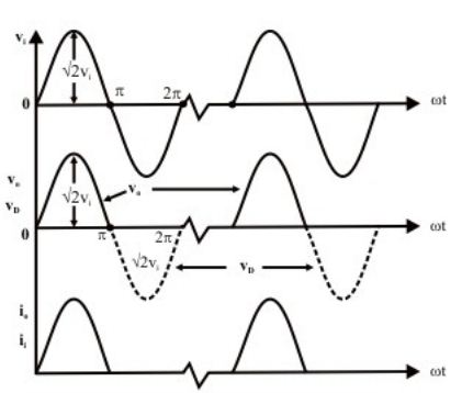
Half-wave rectification is the process occurred in the half-wave rectifier circuitry where the input signal rectification is either dependent on the positive half of the negative half of the cycle. There is a loss of power in this type of rectifier. The output generated consists of AC components that are nothing but the ripples in the circuit. The circuit is not that great efficient for practical applications because its ripple factor is high compared to other rectifiers.
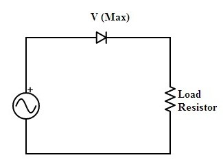
half-wave-rectifier
The operational analysis of the half-wave rectifier circuit can be done based on the above circuit that is a basic half-wave rectifier it consists of semiconductor diode in series with the input AC supply as well as the load is connected in series to the diode. The half-wave rectification is done either based on the positive cycle of the supply or the negative side of the supply as it cannot consider booth at a single duration.
Once the positive side of the cycle considered as per the diode functionality it will be in forwarding bias that results in the establishment of the path for the flow of current and rectification process takes place. If the negative side of the cycle is considered in that case the diode-connected must be reconnected by altering its direction.
Once the diode direction is reversed and necessary changes are made the diode gets interacted to the negative supply of the cycle provided. As per that diode, conduction takes place and the rectification process is further carried out. In the case of positive cycle consideration, the negative cycle is blocked and during the negative cycle consideration, the positive cycle is blocked.
Output Analysis without Capacitor Filter Application
As the output generated because of the above process of half-wave rectification is consisting of ripples in the circuit. Either it may be a positive cycle or negative cycle considered the output generated will be in the form of pulses. As the intention of generating pure DC as it’s output is not gained here. Hence this cannot be sufficient for practical applications.
Analyzing Half Wave Rectifier with Capacitor Filter
As the process described for half-wave rectifier above it will remain the same but the only difference here is to the same circuit of half-wave rectifier a capacitor is connected that will carry the functionality of the filtering of output generated.
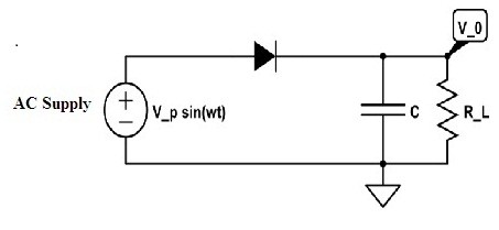
half-wave rectifier with capacitor filter
Output Analysis with Capacitor Filter
The excited DC is obtained from the general half-wave circuit. This is time-varying DC. In order to overcome this problem a capacitor that smoothens the output is connected. It is just like a filtering circuit.
Analyzing Full Wave Rectifier
As there is the problem of loss of power in half-wave rectifier because only one of the cycle consideration and this can be overcome by utilizing both the cycles for rectification. This is the main purpose of a full-wave rectifier. It is further classified as the center-tapped and bridge full-wave rectifiers.
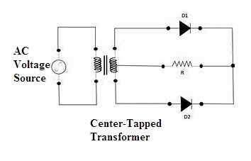
Full Wave Rectifier (Center-Tapped)
This circuit consists of two diodes and the resistive load connected parallel to each other. In addition to it, a center-tapped transformer is present that is a general transformer that has a wire at the center of the secondary winding. But this type of transformer makes the circuitry costliest.
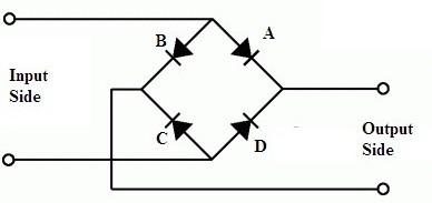
full-wave bridge rectifier basic model
Hence another type of full-wave rectifier is designed that consists of four diodes connected in a bridge topology. So it is referred to as the Bridge rectifier. In this, the diodes are connected in a diagonal manner. The oppositely faced diodes are acting towards the same bias whereas the remaining two are reversed biased. Hence this is the technique behind the bridge rectifier.
Output Analysis of Full Wave Rectifier without Capacitor Across the Load
As both the cycle utilized here without any loss of the power and this increases the efficiency of the circuit. Hence continuity is observed in the output. However, there is the chance of the presence of ripples in the output generated. But compared to half-wave rectifier its ripple factor is less.
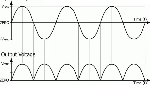
output waveforms of the full-wave rectifier
Analyzing Full-Wave Rectifier with Capacitor Filter
The process of rectification remains the same whether there is a filter connected or not it doesn’t make any difference there. But there is a chance of presence of ripples even in the full-wave rectifier. So in order to make the output ripple-free, a capacitor is connected across the load. Hence this capacitor filter is helpful to remove the ripples and make the output purer.
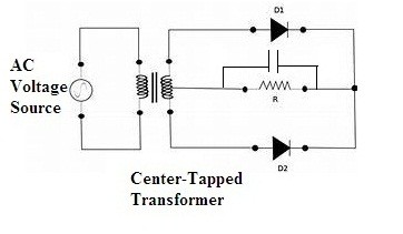
Full Wave Rectifier (Center-Tapped) with capacitor filter
As the capacitor is connected across the load one can see the further changes in the output as follows.
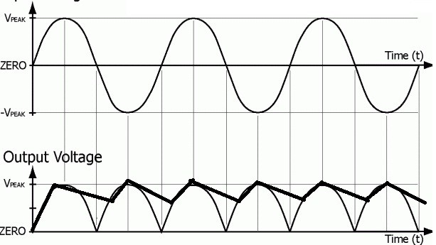
output waveforms of the full-wave rectifier with capacitor filter
Hence the analysis is obtained for the capacitor connected across the half-wave and full-wave rectifiers and then the purpose of the connecting capacitor is proven beneficial because it can remove unnecessary ripples from the generated output. After analyzing the purpose of the capacitor is there any other type of filter that exists or preferred so that it can improve the purity of output?
