A capacitive transducer is one kind of device, used to change the energy from one form to another. Generally, transducers are frequently used at the boundaries of control systems, measurement, & automation, wherever electrical signals are changed from different physical quantities like force, energy, light, torque, position, motion, etc.
There are two kinds of transducers like electrical and mechanical. Electrical transducers convert the physical quantities to electrical whereas mechanical transducer converts physical to mechanical. This article discusses an overview of the capacitive transducer and its working.
What is a Capacitive Transducer?
A passive transducer which is used to measure the pressure, displacement, and other physical quantities is called a capacitive transducer. So this kind of transducer needs additional power for its operation. The working principle of the capacitive transducer is variable capacitances. This transducer’s capacitance will be changed due to several reasons such as overlapping of capacitor plates, distance change in between the two plates & dielectric constant.
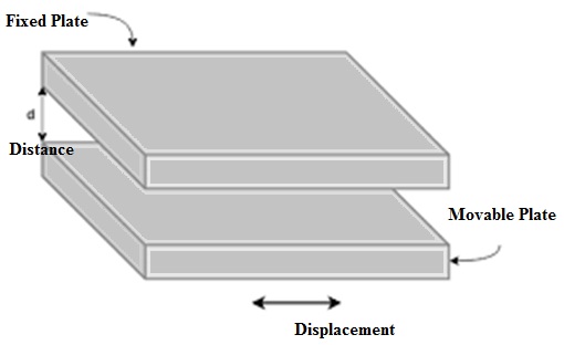
Capacitive Transducer Construction
This transducer includes two parallel metal plates which are divided through the dielectric medium like material, air, liquid, or gas. In the typical capacitor, the main distance between the two plates is stable whereas, in the capacitive transducer, it will be changed.
This kind of transducer utilizes capacitance to change the mechanical movement into a signal. The input quantity can change the capacitance to measure directly by using this transducer. The capacitor can measure both the fixed as well as dynamic changes. And also, the displacement can be measured directly by connecting the computable devices toward the capacitor’s variable plate. It works on two modes like contacting & non-contacting.
Capacitive Transducer Working Principle
The capacitive transducer working principle mainly depends on the parallel plate capacitor’s capacitance. The capacitance of a capacitor is ‘C’ and the area in between two plates is ‘A’ with the distance ‘d’ can be given as
C = ƐA/d
C = ƐoƐrA / d
From the above equation,
‘A’ is the overlapping region of two plates within m2
‘d’ is the distance in between two plates of a capacitor within a meter
‘ε’ is the permittivity of the medium in F/m
εr is the relative permittivity
‘ε0’ is the permittivity of open space
The parallel plate capacitive transducer schematic diagram is shown below.
The change within capacitance mainly happens due to physical variables like displacement, force, pressure, etc. The capacitance of the transducer also alters through the difference in their dielectric constant which is generally because of the gas level or liquid measurement.
The capacitance of the transducer can be measured through the bridge circuit and the transducer’s output impedance can be given as
Xc = 1/2πfc
Where,
‘C’ is the capacitance
‘f’ is the frequency of excitation within Hz.
Working of Capacitive Transducer
The working of a capacitor transducer is discussed below.
By Changing the Overlapping area of the Two Capacitive Plates
The parallel plate capacitor is shown below where these two plates include some width denoted with ‘b’ & that is overlapped with length ‘l’.
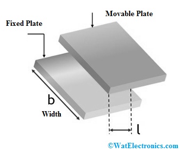
Changing the Overlapping Area
The operating of this capacitor can be done in such a manner that capacitance is comparative to the region of overlapping of the two plates. So, the length of this overlapping can be changed based on the displacement that is to be calculated. Therefore, variation of displacement permits the change within the capacitance.
We already know that a parallel plate capacitor’s capacitance can be given as
C = ƐoƐrA / d
C = ƐoƐrbl/d Faradays
In the above equation, ‘l’ is the overlapping length whereas ‘b’ is the width of the two capacitor plates
The sensitivity can be expressed as
S = 𝛿C/ 𝛿l
So we have
C = ƐoƐrb/d F/m
Therefore, from the above-mentioned equation, we can simply say that the sensitivity is stable. So, a linear curve in between the displacement and the capacitance can be plotted apart from the opening part that is shown below.
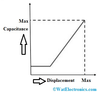
Capacitance Vs Displacement
Thus, by changing the overlapping region of the two plates of a capacitor, linear displacement is gauged precisely in between 5 mm – 10 mm.
By Modifying the Distance among the Two Capacitive Plates
The working of this capacitor is, the capacitance of this capacitor is inversely proportional toward the distance ‘d’ among the two plates to verify the linear displacement.
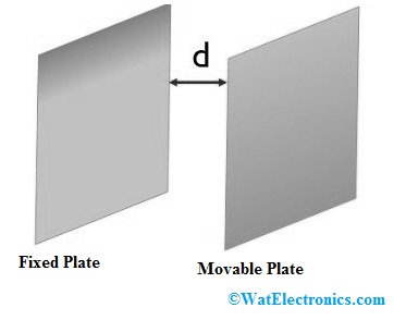
Modifying the Distance
In these types of transducers, in between two capacitive plates, one plate is fixed whereas the other one is movable. Once the movable plate moves, the capacitance will be increased or decreased based on the displacement which is to be gauged.
An ac circuit is mainly used to verify the difference within the capacitance, thus verifying the dislocation of the capacitor plate.
The following graph signifies the non-linear wave in between capacitance & displacement. The curve is nonlinear which is displayed clearly. So by observing the following curve, we can declare that the capacitor is extremely responsive primarily. Therefore, we can say that capacitive transducers are mainly used for verifying extremely little displacement.
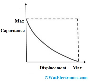
Capacitance Vs Displacement Curve
Therefore, the capacitor’s sensitivity for change within distance can be given as
S = 𝛿C/ 𝛿d = -ƐoƐrA/d2
Therefore we can say that the transducer’s sensitivity changes over a fixed range.
By Modifying the Dielectric Material’s Permittivity
The operating of this transducer can be done by the disparity within the relative permittivity of the dielectric material located in between two plates.
The dielectric material movement among the two plates will decide the capacitance for the displacement. The following diagram will signify a transducer throughout the difference of relative permittivity.
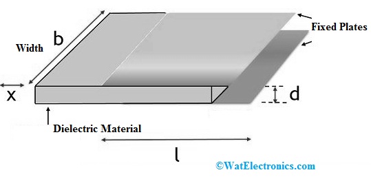
Changing the Permittivity in Capacitive Transducer
In the image above, the distance between two plates is denoted with ‘d’ and the width of every plate is denoted with ‘b’ & the dielectric material’s displacement is denoted with ‘x’ & the overlapped region is denoted with ‘I’.
The capacitance equation for the capacitive transducer can be given as
C = (Ɛobl1/d) + (ƐoƐrb(l-l1)/d)
C = Ɛob/d [l1+Ɛr (l-l1)]
The capacitance can be changed from C to C – ∆C through the dielectric material’s movement above a ‘x’ distance
C – ∆C = Ɛob/d [(l1+x)+ Ɛ0 Ɛrb/d(l-(l1+x)]
C – ∆C = Ɛob/d [(l1+x)+ Ɛl- Ɛr(l1+x)]
By simplifying the above equation, we can get
∆C = Ɛobx/d (Ɛr-1)
Therefore we can declare that the difference in capacitance illustrates proportionality by the displacement that is to be calculated. Usually, by using this technique, a displacement which ranges from 1μm – 10 mm can be calculated
Advantages
The advantages of capacitive transducer include the following.
- The loading effects exhibited by a capacitive transducer are less because it provides very high input impedance.
- This transducer’s frequency response is outstanding.
- Very sensitive
- It gives high resolution
- These transducers use less power
- This transducer works with less force & thus used in small systems.
- These transducers are extremely responsive, so their accuracy is 0.005%.
- By using these transducers, the order of 2.5×10⁻³ resolution can be easily attained
- This transducer measurement
- Measurement of this transducer can be affected through the stray magnetic field but this transducer is not affected.
Disadvantages
The disadvantages of capacitive transducer include the following.
- A complex measuring circuit is necessary at the output is needed because of the high output impedance.
- To decrease the pickup chances, electrostatic screening should be specified to these kinds of transducers.
- The change within exterior factors such as humidity, temperature, it holds back the capacitance for the transducers.
- The capacitance of this transducer may change because of moisture, dust, etc.
- These are temperature sensitive, so any modification within temperature can affect their performance badly.
- This transducer shows non-linear performance many times because of the effect of edges. So to eliminate this effect, guard rings are used.
- When the cable is connected to the transducer while measuring small physical changes then it is a source of error.
- The output impedance of this transducer is fairly high because of less capacitance value which leads to a loading effect. Here, the output impedance mainly depends on the signal’s frequency used for the capacitance measurement.
Applications
The applications of capacitive transducers include the following.
- These transducers measure both linear as well as angular displacements through high sensitivity.
- These are mainly used to measure pressure and force. These are first changed into linear displacement first & after that, the displacement can be measured through this transducer.
- This transducer is used to gauge the level of volume, liquid, density, etc. But, these parameters can be measured through a mechanical modifier.
- This transducer is directly used for measurement of pressure wherever change within pressure results in equivalent change within dielectric medium constant among the two plates of the capacitor.
- The gases of dielectric constant modify through humidity. So, this transducer can gauge the humidity within gases by using the change within capacitance because of the change within the principle of dielectric constant.
Know more about Transducer MCQs.
Please refer to this link to know more about Capacitive Transducer MCQs
Thus, this is all about an overview of capacitive transducers. We know that the main function of a transducer is to change the energy from one form to another. A capacitor transducer is used to determine different quantities such as pressure, temperature, displacement by measuring the difference within the capacitance of a two-plate capacitor. Here are a few questions for you: what are the different types of capacitive transducers? What is an Inductive Transducer?