TRIAC or Triode for Alternating Current is a three-terminal AC device that is used mainly for switching AC. Generally, TRIACs are made with two SCRs which are connected in a reverse-parallel arrangement by gates coupled to each other. TRIACs and SCRs are different because, in TRIACs, it allows the flow of current in both directions whereas an SCR allows current in only a single direction. Most TRIACs are activated by providing either a positive (+ve) or negative (-ve) voltage to the gate terminal whereas SCR needs a positive voltage. Similar to SCRs, these components handle much higher currents. This article provides brief information on BT139 TRIAC, pin configuration, specifications & its applications.
What is BT139 TRIAC?
BT139 is a sensitive gate, passivated, and four quadrant TRIAC available in a TO-220AB package. The BT139 TRIAC handles loads with moderate power switching as high as 1600V & 16A. This TRIAC is mainly used in general-purpose phase control & bidirectional switching applications. This device has the capability to work within four quadrants, so it can switch both positive & negative currents and work with a positive/negative gate current.
Working
The working of this TRIAC is, whenever the gate terminal of this TRIAC is triggered, and then it will become conductive by allowing the flow of current throughout the device. The TRIAC conducts continuously until the flow of current drops under a certain threshold value, upon which it will turn off. These TRIACS are used widely because of their low cost & high-power handling ability so these are very popular choices for consumer & industrial-based applications wherever AC switching is necessary.
Pin Configuration:
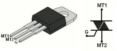
The pin configuration of BT139 TRIAC is shown below. This IC includes three pins which are discussed below.

BT139 TRIAC Pin Configuration
- Pin -1 (MT1): This pin is used to provide current & obtaining from the device.
- Pin -2 (MT2): This pin helps in transmitting current in & out.
- Pin-3 (Gate): This gate pin is used to change the flow of current between the primary two pins.
Features & Specifications:
The features and specifications of BT139 TRIAC include the following.
- The type of thyristor is TRIAC.
- It has a high voltage blocking capacity.
- Direct triggering from logic ICs & low power drivers.
- It has a sensitive gate terminal.
- It is planar passivated mainly for reliability & voltage ruggedness.
- It triggers within four quadrants.
- Its peak gate power is 5 watts.
- Its operating temperature ranges from -40°C to +150°C
- It includes three pins.
- Its case or package type is TO-220AB.
- The type of termination is through hole.
- Its maximum gate trigger current or Igt is 35mA.
- Its maximum holding current (Ih) is 45mA.
- Its maximum repetitive reverse voltage or Vrrm is 800V.
- It has a 600V breakdown & 16V continuous current capacity.
- Its power dissipation is 20W.
- Its maximum gate trigger voltage (Vgt) is 0.7V.
- Its On-state RMS current is 16A.
- Its peak nonrepetitive surge current is 155A.
- Other BT139 TRIACs are; the BTA13x series, MAC97A & BTAxx series.
Solid State Relay Circuit with BT139 TRIAC & MOC3021 Optoisolator
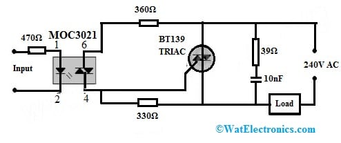
The solid-state relay circuit using BT139 TRIAC & MOC3021 optoisolator is shown below. For any TRIAC, an appropriate heat sink is mandatory. Solid state relays have many benefits as compared to an electromagnetic relay are; very quick switching speed, reliability, control of o/p current, less noise, drive from 5mA of low current, and drive from 3.6V DC voltage.
The required components to make this circuit mainly include; an MOC3021 Optoisolator, BT139 TRIAC, 10nF Non-polar Capacitor, 470Ω, 330Ω, 39Ω, 360Ω, Resistors, 220V to 240V AC supply and load. Connect the circuit as per the circuit shown below.

Solid State Relay Circuit with BT139 TRIAC
Working
This solid-state relay circuit is mainly designed for switching both AC/DC currents through TRIAC. This simple circuit uses BT139 TRIAC to drive 1000 watts of an AC load easily. This circuit uses the MOC3021 Optocoupler to separate the input part from the output part. The MOC3021 Optocoupler could function with any TTL device however an external TRIAC is suggested to work it correctly through high load because of some safety measurements & different magnitudes.
The main features of this IC are; that the device stability is consistent for any high load, and the output pins of this IC is capable of holding the maximum load at off condition so that it is reliable at a normal level for any kind of switching device.
This IC has an internal IR transmitting function so that the input device is used very securely with this IC. This IC provides different magnitude outputs because of non-zero capability. This IC operates within the high temperature when we need to control maximum load & it can also store the temperature.
The input for this circuit can be taken from any source of CMOS IC, Arduino, or any microcontroller. Here Optocoupler’s output performs as a gate trigger mainly for BT139 TRIAC. Whenever at the gate terminal there is a trigger pulse the circuit acts as a closed switch & as a result, it allows the current flow toward the load. Always connect a heat sink to a TRIAC. This simple SSR circuit is capable of driving from the 5mA or below current driving from 3.6V DC voltage.
These circuits are very helpful for controlling AC power. It can also be used for controlling the power to control the speed of the motor, fan dimming, motor, and power switching. These circuits are used to drive electric heaters to control the temperature and are also used in High-load switching.
Please refer to this link to know more about TRIAC – Structure and Its Operation.
Applications
The applications of BT139 TRIAC include the following.
- These TRIACs are used in AC load switching, pulse width modulators, medium power switching, heating, motor control, static switching, lighting in the domestic and industrial sectors, etc.
- This TRIAC is used for low-power switching circuits
- It can be used as a switch mainly for AC loads.
- This IC can be used with logic ICs, microcontrollers & low-power-based gate trigger circuits.
- This is a general-purpose TRIAC generally used in phase control & switching applications.
- These are appropriate for coupling directly to HTL, TTL, CMOS & different applications like; a variety of logic functions, and low-power AC switching applications like; small light controllers, fan speed, etc.
Please refer to this link for the BT139 TRIAC Datasheet.
Thus, this is an overview of BT139 TRIAC, pinout, specifications, circuit, working, and applications. The BT139 TRIAC is capable of regulating the value of power for different loads from 600 volts to 16A. These TRIACs have many benefits like; triggering directly from logic ICs & low-power drivers, sensitive gates, high voltage blocking ability, triggering within all four quadrants, and planar passivation for reliability & voltage ruggedness. These are commonly used for motor speed control, industries & heating through static switching circuits. Here is a question for you, what is BT136 TRIAC?