The ambient light sensor is one of the types of optical sensors used to detect the change in light intensity. It is used in mobiles, cars, Televisions, cameras, etc. For example, an ambient light sensor in mobiles adjusts the display brightness based on the change in light intensity. In cars, it is used to turn ON the headlights during outdoor dark lighting conditions. There are different types and series of ambient light sensors available in the market. They are photodiodes, phototransistors, photonic integrated circuits, BH1750, LDR sensors, and TCS3200. The equivalents of BH1750 ambient light sensors are BH1750VI, VEML6305 TSL2561. This article explains how to interface a BH1750 ambient light sensor with a microcontroller (ATmega328p) using Arduino UNO.
Features of BH1750 Ambient Light Sensor:
Adjusts the brightness of the mobile phones and LCD displays based on environmental lighting conditions or changes in the intensity of light.
- Has in-built I2C communication interface (SDA and SCL pins) to interface with microcontroller.
- In-built illuminance (analog input) to digital converter.
- Requires operating voltage of 2.4V to 3.6V and consumes less current of 0.21mA.
- Wide range of detection at high resolution (1 to 65536 lx).
- 2 devices can be connected to the I2C interface in the sensor.
- Doesn’t require external components.
- Does not depend on the light source applied and influences very small IR radiation.
- It gives the lux (illuminance) values directly (calculation not required).
Technical Specifications
The following are the technical specifications of the BH1750 ambient light sensor,
- It can support an intel-integrated bus interface (I2C).
- Spectral responsibility is approximate to the eye response of humans.
- Logic input voltage – 1.8V.
- Low current by power down function.
- High and wide range resolution – 1 to 65535 lx
- Light noise rejection – 50Hz/60Hz
- Supply voltage- 4.5V.
- Operating temperature- 40°C to 85°C.
- Storage temperature- 40°C to 100°C.
- Power dissipation- 400mA.
- SDA sink current Imax- 7mA.
- Maximum VCC voltage- 3.6V.
- I2C reference voltage- 1.65V.
- Supply current- 120 to 190 microamps.
- Measurement accuracy- 1.44 times.
- SCL clock frequency- 400KHz.
- I2C bus free time- 1.3microseconds.
Pin Diagram of Ambient Light Sensor:
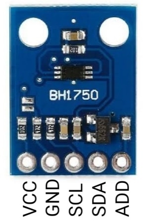
Here, the BH1750 ambient light sensor module is taken for interfacing with Arduino UNO. It is developed by ROHM semiconductors based on the IC BH1750FVI digital ambient light sensor. It is available in 16-pin built-in illuminance to digital converter IC. It works on the IIC or I2C bus interface. The pin diagram of the BH1750 ambient light sensor module with 5-pins is shown in the figure below.

BH1750 Ambient Light Sensor Module
VCC: This pin refers to the supply pin, which provides a power supply of 2.4V to 3.6V.
GND: This pin refers to the common ground connection.
SCL: This pin refers to the serial clock line, which provides clock pulses for I2C communication.
SDA: This pin refers to the serial data address, which transfers the information via I2C communication.
ADD: This pin refers to a device address, which is used to select the address when more than 2 modules are connected.
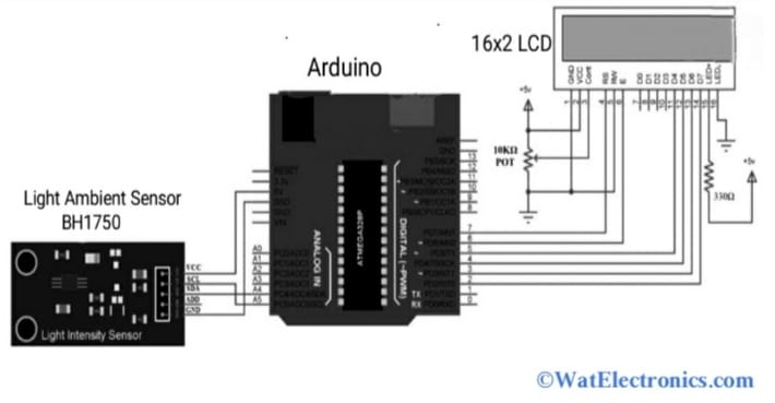
The circuit diagram of the BH1750 ambient light sensor interfacing with a microcontroller using Arduino UNO is shown in the figure below. The required components are;
- Ambient light sensor BH1750.
- Arduino UNO.
- 16×2 LCD.
- 330 Ohms resistor.
- 10 Kilo Ohms potentiometer.
- Breadboard and wires for connection.

Make the connections as per the above interfacing circuit diagram. The ambient light sensor module BH1750 interfaces or can communicate with a microcontroller over an I2C communications bus to sense the light ambient data. The pins A5 & and A4 are the Arduino’s I2C pins used for interfacing.
Connect the +5V pin and GND pin of the Arduino to the VCC and GND pins of BH1750. The A4 & A5 pins of the Arduino are connected to the SDA & SCL pins of BH1750. The LCD pins D4 to D7, RS, and E are connected to the digital I/O 7 to 2 pins of the Arduino UNO. To adjust the contrast of the display, a 10 KiloOhms potentiometer is connected to the LCD as shown in the figure.
The ADD pin of BH1750 can be either connected to GND Or left open, which makes the pin LOW and the sensor’s I2C slave address becomes 0x23. If the ADD pin is HIGH, then the I2C slave address becomes 0x5C. Therefore there is a chance to connect 2 BH1750 ambient light sensors (one pin is HIGH and the other pin is LOW). Upload the following Arduino code to display the result on LCD.
Code to interface BH1750 to Arduino:
/*
Connection:
BH1750 – Arduino
——————
VCC – 5v
GND – GND
SCL – SCL(Analog Pin 5)
SDA – SDA(Analog Pin 4)
ADD – NC (or GND)
*/
#include <Wire.h>
#include<LiquidCrystal.h>
int BH1750address = 0x23;
byte buff[2];
LiquidCrystal lcd (7,6,5,4,3,2); //RS, E, D4, D5, D6, D7
void setup()
{
Wire.begin();
//Serial.begin(9600);
lcd.begin(16,2);
lcd.print(” BH1750 Light “);
lcd.setCursor(0,1);
lcd.print(“Intensity Sensor”);
delay(2000);
}
void loop()
{
int i;
uint16_t value=0;
BH1750_Init(BH1750address);
delay(200);
if(2==BH1750_Read(BH1750address))
{
value=((buff[0]<<8)|buff[1])/1.2;
lcd.clear();
lcd.print(“Intensity in LUX”);
lcd.setCursor(6,1);
lcd.print(value);
//Serial.print(val);
//Serial.println(“[lux]”);
}
delay(150);
}
int BH1750_Read(int address)
{
int i=0;
Wire.beginTransmission(address);
Wire.requestFrom(address, 2);
while(Wire.available())
{
buff[i] = Wire.read();
i++;
}
Wire.endTransmission();
return i;
}
void BH1750_Init(int address)
{
Wire.beginTransmission(address);
Wire.write(0x10);
Wire.endTransmission();
}
The ambient light data from the I2C bus of the BH1750 sensor is extracted by Arduino and shows the result on LCD. That means the data will be transferred to the Atmega328p microcontroller via I2C pins of the sensor (SCL and SDA pins). The 16×2 LCD is interfaced with the Arduino board to display the output result of BH1750.
Applications of BH1750 Ambient Light Sensor:
A few applications of the BH1750 ambient light sensor are given below,
- LCD televisions
- Mobile phones
- Cars
- LCD displays
- Portable gaming devices
- Digital cameras
- Video recorders
- PCs
- Notebooks
Please refer to this link for the BH1750 ambient light sensor datasheet.
Thus, this is all about an overview of interfacing the BH1750 ambient light sensor with an Arduino microcontroller (ATmega328p). To interface with any microcontroller and obtain the illuminance (lux) values, the BH1750 uses the I2C bus interface . Check the specifications from the data sheet and select the suitable ambient light sensor for the application.