The BD140 PNP transistor was manufactured originally by Phillips and rated at 160MHz for use in particular audio applications. After that, these transistors were cloned simply by other electronic manufacturer companies like ON Semi, ST, Samsung, etc. Generally, there are well-known medium power PNP transistors available like BD136 & BD140 which are used in various electronic circuits. This article provides brief information on the BD140 Transistor, pinout, specifications, circuit, and its applications.
What is BD140 Transistor?
The BD140 transistor is a medium power, PNP power transistor that is used mostly in audio amplifiers & also drivers that use quasi-complementary/complementary circuits. These PNP transistors are made up of silicon material and available in the TO-126 package. This PNP transistor handles up to 1.5A of current to drive loads within electronic circuits up to 1.5A like; relays power LEDs, motors, and many more.
The high collector-emitter (CE) & collector-base (CB) voltage of the BD140 transistor is 80 Volts. This transistor’s least saturation voltage is -0.5V and the collector dissipation is approximately 12.5 W so it is perfect to be used within audio amplifier circuits. This transistor’s Beta value ranges from 40 – 160 which decides the device’s amplification factor. The highest base-to-emitter voltage of this transistor is 5V, so it can be used properly within the embedded system for logic-level application.
Working
The BD140 PNP power transistor is extremely versatile to use in several applications. Whenever a positive voltage is provided to the base terminal of this transistor, then both the collector & emitter terminals will be left open. When there is no voltage available at the base terminal then it will close.
When the BD140 PNP transistor is in a biased state, it allows 1.5A of current maximum throughout its EC (emitter-collector) junction, which is known as the saturation state When above 1.5A current flows through the EC junction then it can harm the circuit. Once the base current is detached this transistor will become completely off which is known as the Cut-off Region thus there is no flow of current throughout the circuit.
Pin Configuration:
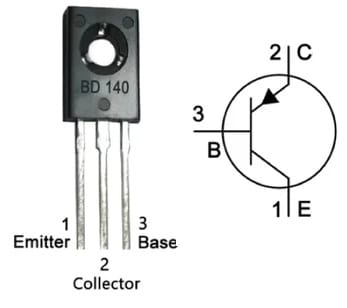
The pin configuration of the BD140 transistor is shown below. This transistor has three terminals like a BJT which are discussed below.

BD140 Transistor Pin Configuration
- Pin-1 (Emitter): The flow of current will drain out through this terminal and is connected usually to GND.
- Pin-2 (Collector): The current flows throughout this terminal and is connected normally to load.
- Pin-3(Base): This terminal controls the transistor biasing, so used to switch ON/OFF the transistor.
Features & Specifications
The features and specifications of the BD140 transistor include the following.
- The type of transistor is PNP.
- Contact plating is Tin.
- The type of mounting is Through Hole.
- It has three pins.
- The material of the transistor element is Silicon.
- Length x Height x Width is 7.8mm x 10.8mm x 2.7mm.
- This PNP transistor is a moderate current device that works with the medium power in different circuits.
- The total gain value of this transistor ranges from 25 to 250hFE.
- The collector current is -1.5A, where the negative at the current value specifies it is a PNP transistor,
- The base current of this transistor is -0.5A which is the maximum acceptable base voltage to activate the transistor.
- The power dissipation of this is 12.5W, which specifies the peak power dissipation value that is permissible on a transistor.
- The transition frequency is 190MHZ.
- The junction temperature is 150°C.
- This transistor uses a TO-126 package and is in rectangular shape where this package is made with epoxy & plastic.
- The voltage from collector to base or VCB is -80V.
- The voltage from collector to emitter or VCE is -80V.
- The voltage from the emitter to the base or VEB is -80V.
- The continuous collector current or IC is -1.5A.
- Its base current or Ib is -0.5A.
- The breakdown voltage from emitter to base or VBE is -5V.
- The equivalent BD140 transistors are; BD170, BD140G, BD180, BD790, BD231, BD792, BD792, BD238G, MJE702, MJE171. The complementary BD140 NPN transistor is BD139. Every equivalent transistor in the above-mentioned is extremely related to each other, so the specifications of all these transistors are also the same. Simultaneously, we need to estimate the voltage & current values of each transistor before replacing the bd140 transistor with any of them.
How to use BD140 Transistor safely within a Circuit?
To run the BD140 transistor very securely within a circuit for a long time, it is necessary to not operate this transistor above its maximum ratings. It should not be operated from a higher voltage than 80V DC and always utilize a suitable heatsink, To provide the necessary base current to this transistor, use an appropriate base resistor. This transistor does not store or operate in temperature once -55 centigrade & above +150 centigrade.
DC Motor Controlled by Sound with CA3140 IC & Transistors
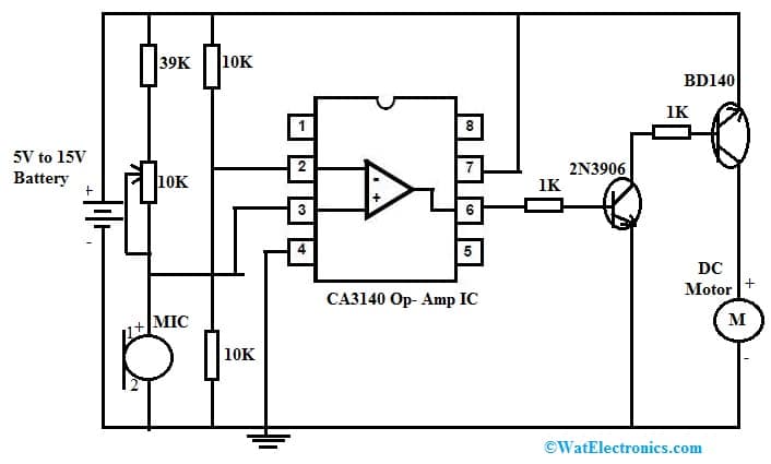
There are different methods available for controlling DC motors. Among them, a sound-controlled motor is one of the controlling techniques. Here we are going to build a sound-controlled motor circuit with CA3140 IC. To activate the motor, the voice signals are used using a microphone. In this circuit, IC CA3140 is working within comparator mode.
The required components to make this circuit mainly include; a 5V to 15V battery, 2N3906 NPN transistor, CA3140 Opamp IC, DC motor, BD140 PNP transistor, Electret Mic, 1K, 10K & 39K resistors, and 10K variable resistor. Connect the circuit as per the circuit shown below.

DC Motor Controlled by Sound with CA3140 IC & Transistors
Working
This sound-controlled motor circuit mainly uses CA3140 op-amp which works in comparator mode. This simple circuit can be functioned by using a wide range of DC supply that ranges from 5V-15V. In this circuit, a 10K variable resistor is mainly used for adjusting the circuit’s sensitivity. When any voice signal is there on the microphone, then the CA3140 comparator will produce a signal. The transistors used in this circuit are; BD140 & 2N3904 which are allied with pin-6 of op-amp to strengthen the o/p signal. This generated signal is used to turn ON a DC-connected motor. The current output status can be indicated by connecting a lead to the emitter terminal of the transistor.
This circuit is used to control the DC motor through sound and is used in different applications. It is also helpful for blind people in controlling home appliances because they don’t want to find the switch for controlling the motor. This simple circuit can also be used in different toys and also in robotics.
BD140 Transistor Applications
The applications of the BD140 transistor include the following.
- The BD140 transistor is used in educational, beginner electronics projects & industrial electronics.
- They are used in analog circuits, microcontroller projects & Arduino projects, etc.
- This transistor is used to drive different loads below 1.5A in electronic circuits like relays, high-power LEDs, motors, etc.
- This transistor is applicable in battery chargers, motor drivers, audio amplifiers, driver stages within Hi-fi amplifiers, switching circuits, power supplies, TV circuits, Darlington pair, astable, bistable multivibrators, multi-vibrator circuits, audio amplifiers, high current relay driver, lighting systems, microphone preamplifiers, signal amplifiers and many more.
Please refer to this link for How to Select a Transistor.
Please refer to this link for BD140 Transistor Datasheet.
Thus, this is an overview of the BD140 Transistor, pin configuration, specifications, circuit, working, and its applications. Here is a question for you, what is a BD139 transistor?