In 1999, the ATMEL introduced ATtiny Microcontrollers. There are several 8-pin based ATtiny microcontrollers are available like ATtiny11, ATtiny12, ATtiny22, ATtiny26, ATtiny24, ATtiny44, ATtiny84, ATtiny25, ATtiny45, ATtiny202/204/402/804/404 & ATtiny85 microcontroller with microchip technology. These microcontrollers became popular as tiny AVR controllers.
These are designed in small size with all the features of a microcontroller. They contain few Input-Output pins and limited program memory (data memory and SRAM is less). These are fully loaded with various features and multi-functional I/O pins. This article gives a brief description of pin configuration, technical specifications, and circuit diagram of the ATtiny85 Microcontroller.
What is a ATtiny85 Microcontroller?
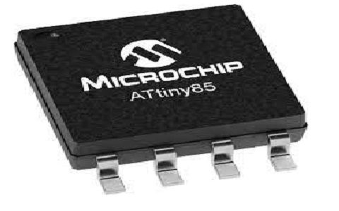
ATtiny85 Microcontroller is a small 8-pin AVR microcontroller with high performance and is based on RISC advanced CPU architecture. It is available in 2 package types, which are used to interface and control various devices and sensors. It consumes low power and is available in small size with a program memory size of 8 Kbytes, EEPROM, and RAM of 512 Kbytes to store the code of the given instruction.
The main safety feature of this microchip is that the watchdog timer makes wide use in embedded and automation systems. It is one of the popular microcontrollers with many features. It is a microcontroller with a small size and can run different program codes.

ATtiny85 Microcontroller
It is also known as a small Arduino chip with few I/O pins, limited flash/program memory, SRAM, and EEPROM. For a small code, the ATtiny85 microcontroller chip is used instead of using ATmega328p or Arduino board. To get input from sensors, 3 pins are used as analog inputs from these limited I/O pins.
ATtiny85 Pin Configuration
The ATtiny85 microcontroller is a small 8-pin AVR controller. It has 8 I/O pins, in which 6 I/O pins are used for multiple functions and the other 2 pins are power pins used for VCC and GND. These 6 I/O pins are also known as PORTB pins, which are used as inputs or outputs based on the application.

ATtiny85 Pin Configuration
According to the datasheet of ATtiny85, the PORTB pins are labeled as PB0, PB1, PB2, PB3, PB4, and PB5. The power pin VCC is connected to the supply and the GND pin is connected to common ground.
The pin diagram of the ATtiny85 microcontroller is illustrated in the figure below. The ATtiny85 pin configuration with related functions is given in the tabular form.
|
Pin Name |
Pin Configuration |
Pin Description |
| PORTB Pin 1 | PB5 (PCINT5, ADC0, dw, RESET) | Bidirectional I/O pin interrupt pin, reset pin, analog channel 0, define the word, reset pin, for bootloader reprogram and remove |
| PORTB Pin 2 | PB3 (XTAL1, CLK1, ADC3, OC1B, PCINT3) | Bidirectional I/O pin, interrupt pin 3, crystal oscillator pin 3, clock 1, analog channel 3. For USB programming, PWM, analog input, XTAL input |
| PORTB Pin 3 | PB4 (XTAL2, CLK0, ADC2, OC1B, PCINT4) | Bidirectional I/O pin, interrupt pin, clock 0, crystal oscillator 2 for USB programming, PWM, analog input, and XTAL output |
| PORTB Pin 4 | GND | Ground pin. It is the negative supply given to the chip |
| PORTB Pin 5 | PB0 (MOSI, AINO, OC0A, OC1A, D1, SDA, AREF, PCINT0) | Bidirectional I/O pin works as PWM output, SPI, and I2C (serial data) communication |
| PORTB Pin 6 | PB1 (MISO, AIN1, OC0B, OC1A, D0, PCINT1) | Bidirectional I/O pin, used for PWM output and SPI data output |
| PORTB Pin 7 | PB2 (SCK, ADC1, T0, SCL, PCINT2) | Bidirectional I/O pin, used for analog input and SCK for SCL and SPI data |
| PORTB Pin 8 | VCC | A positive power supply is given to the chip. Usually 5 Volts. |
Specifications
ATtiny Microcontroller Specifications or Features are as follows
- It is an advanced RISC architecture design with high performance.
- It uses an 8-bit CPU
- It has 8 number of Input-Output (I/O) pins
- It contains 8 programmable Input-Output (I/O) pins
- Its operating voltage ranges from +1.8Volts to +5.5Volts and +2.7Volts to +5.5Volts (absolute supply voltage is maximum +6Volts)
- The DC current per I/O pin is of a maximum of 40mA.
- The DC current flow through GND and VCC pins is of a maximum of 200mA
- It operates at a temperature of -55°C to +125°C
- Communication Interfaces
- For programming ATtiny Microcontroller, master/Slave SPI Serial Interface is used (5, 6, and 7 pins)
- For connecting sensors and peripheral devices, I2C or Two-Wire Serial Interface is used. (5 and 7 pins)
- To communicate with other controllers, Universal Serial Interface is used. (5, 6, and 7 pins)
- It doesn’t contain UART Interface
- It has 4-channels with 10-bit ADC resolution
- It has one Analog Comparator
- It contains Two 8-bit counters, which work as a timer module.
- The number of PWM outputs are 4
- The frequency range of the external oscillator is 0-20MHz (For ATtiny 85) and 0-10MHz (For ATtiny85V)
- The frequency range of the internal oscillator is 0-8MHz with an internal calibrated R-C oscillator
- The speed of the CPU is 1MBPS (1MHz)
- The size of the flash memory or program memory is 8Kbytes (10000 erase/write cycles)
- The size of the RAM is 512 Bytes on Internal SRAM
- The size of the EEPROM is 512 Bytes of In-system programmable EEPROM
- It contains a program lock and watchdog timer
- It has 3 power save modes such as power down, ADC noise reduction, and Idle modes.
- It contains 32 registers.
- In an operating mode of 1.8V, the current consumption is 300 microAmps. While in the power-down mode of 1.8V, the current consumption is 0.1 microAmps.
- It contains a 10-bit ADC with 4 channels.
Alternative ATtiny85 Microcontrollers are; ATtiny45, ATtiny25, ATtiny25V, ATtiny85V, ATtiny45V microcontrollers are the alternative ATtiny85 microcontrollers.
ATtiny45 microcontroller is a popular and very cheapest 8-pin AVR controller based on RISC advanced architecture and developed in AVR IDE. It contains a program memory size of 4 Kbytes. It has several modes of power-saving so that it can be used in mobile embedded systems. It provides high performance with a low power controller.
Circuit Diagram/How to Use?
To learn how to use the ATtiny85 Microcontroller, consider an example of an LED blinking project. In this project, the LED circuit can be built using an ATting85 microcontroller. It blinks/flashes the digital device like LED can be ON and OFF continuously at the predetermined time interval.
The ATtiny85 microcontroller has 6 input/output pins (I/O pins) with 2 power pins of VCC and GND. That means, it is possible to connect 6 output devices to this chip. In this LED blinking project example, only 1 LED is connected to the microcontroller and it helps to know how to turn it ON and OFF. The components required to design this circuit are,
- ATtiny85 Microcontroller
- LED
- Resistor with 47O Ohms resistance.
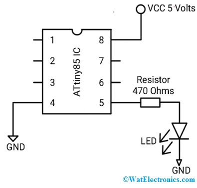
The circuit diagram of the LED blinking circuit with the ATtiny85 microcontroller is shown below.

LED Blinking Circuit with ATtiny85
The supply of 5 Volts is connected to pin VCC (pin 8) to power up the ATtiny85 microcontroller chip. While the pin GND (pin 4) is connected to the ground. The PORTB I/O pins are used as output pins. One end of the 470 ohms resistor is connected to the output pin PBO (pin 5) of the ATtiny85 and the other end is connected to the anode terminal of the LED and while the cathode terminal is connected to the ground.
Here we are using only 3 I/O pins out of 6 I/O pins. This connection provides the necessary supply to the LED. Since LED requires only 10-20mA of current and it doesn’t need more power. These are all the connections required to turn ON and OFF the LED with the help of the ATtiny85 microcontroller chip.
When the digital device (LED) is connected to the PORTB pins (I/O pins) of the ATtiny85 chip, the positive power is provided by these pins to the output device. So, the other end of the LED is connected to the ground.
The code required to turn ON and OFF the LED Or blink the LED using the ATtiny85 microcontroller is given below.
#include <avr/io.h>
#include <util/delay.h>
int main(void)
{
while(1)
{
DDRB= 0xff; // all the pins are set as output pins.
PORTB= 0xff; // all the PORT B pins are set to HIGH
_delay_ms(1000);// turns ON the LED for a second
PORTB= 0x00;//turns OFF the LED
_delay_ms(1000);// turns OFF the LED for a second
}
}
It is important to include the library function, that is #include<avr.i/o.h>. After that, the main loop is created, which contains the infinite loop that is the while(1) loop. Therefore the code of the program is executed continuously again and again.
To make all the I/O pins of the ATtiny85 chip as output pins, the DDRB pin is stated as 0xff in the loop.
To set all the outputs HIGH (turns ON the outputs), PORTB= 0xff. Hence the output device LED, which is connected to the PBO turns ON. A delay of 1000 is used to produce a delay of half a second.
To create a delay, the function _delay_ms() is given. The numerical value given in the delay function represents the delay in milliseconds. For example, a number of 500 produces a delay of 500 msec, ie., half a second (for 0.5 sec, 0.5×1000 = 500 msec) Similarly, 1000 numbers produce a delay of 1000 msec, ie., one full second. Note that one second = 1000 msec. That means, from the given code, the LED turns ON for a second and then turns OFF.
To turn all the outputs of ATtiny85 and LED output OFF, the PORTB = 0xff code is declared. After that, a delay of 1000 msec is given to turn OFF the LED for a second.
This loop is started again and continues forever to turn ON the LED for a second and then turn OFF the LED for a second. Until the power is OFF, the circuit performs this operation by blinking the LED.
Where to Use ATtiny85 Microcontroller/Applications
The applications of the ATtiny85 Microcontroller are given below.
- Used in weather sensing systems
- Used in Solar based applications
- Used in Health and medical equipment
- Used in controlling systems of Industrial machinery.
- Used in automobile and IOT related applications
- Used in the charger, power supply, and power regulating systems
- Used in solar-based systems
- Used in Security systems
- Used in wireless communication systems
- Used in drivers, display units like LCD and LED, peripheral interfacing systems, measurement, and manipulation of analog signals.
- Used in various embedded systems like vending machines, coffee machines, etc.
- Used in hobby projects and development boards
- In robotics
- Power management and monitoring systems
- In AVR control systems of aeronautical technology
Thus, this is all about an overview of ATtint85 microcontroller – definition, pin diagram/pin description, circuit diagram/how to use, specifications, where to use/applications. Here is a question for you, “What are the technical specifications of the ATtiny45 Microcontroller?