ATmega328P microcontroller is created by Atmel within the megaAVR family after Microchip Technology acquired Atmel Corporation in 2016. This is the most popular microcontroller as compared to all AVR microcontrollers because this chip has been featured as a major part of Arduino boards for many years. This ATmega328P microcontroller is an affordable, high-performance & low-powered microcontroller based on an 8-bit RISC processor core. So, this microcontroller is the best choice for different applications. This article discusses an overview of the ATmega328P Microcontroller.
What is ATmega328P Microcontroller?
ATmega328P is an 8-bit, low-power, and high-performance microcontroller from the AVR family of Microchip based on AVR RISC architecture. This is very famous in all AVR controllers because it is utilized within ARDUINO boards. This is mainly designed to use in embedded systems as well as Arduino-based electronic projects. This ATmega328 microcontroller provides huge flexibility for interfacing with peripherals & sensors because of its many features like 8-bit RISC architecture including 32-KB of Flash memory, EEPROM – 1KB & SRAM – 2KB, flexible I/O ports, UART & timers.
Pin Configuration:
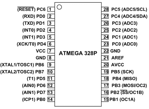
The pin configuration of the ATmega328P microcontroller is shown below. This microcontroller includes 28 pins which are discussed below.

ATmega328P Pin Configuration
- Pin-1 (PC6/ Reset): This pin is used to reset the ATmega microcontroller.
- Pin-2 (PD0/Digital Pin (RX)): This is the i/p pin used for serial communication.
- Pin-3 (PD1/Digital Pin (TX)): This is the o/p pin used for serial communication.
- Pin-4 (PD2/Digital Pin): This pin is utilized like an external interrupt 0.
- Pin-5 (PD3/Digital Pin (PWM)): This pin is utilized as an external interrupt 1.
- Pin-6 (PD4/Digital Pin): This pin is utilized for exterior counter source Timer0
- Pin-7 (Vcc/Positive Voltage): It provides a positive supply to the microcontroller.
- Pin-8 (GND): This is the ground pin of the microcontroller.
- Pin-9 (XTAL/Crystal Oscillator): This pin is connected directly to one of the crystal oscillator pins to give an external CLK pulse to the controller.
- Pin-10 (XTAL/Crystal Oscillator): This pin is connected to the remaining pin of the crystal oscillator to give an exterior CLK pulse to the controller.
- Pin-11 (PD5/Digital Pin (PWM)): This pin is used mainly for Timer1 of the external counter source.
- Pin-12 (PD6/Digital Pin (PWM)): This pin is a +ve analog i/ps of the comparator.
- Pin-13 (PD7/Digital Pin): This pin is a -ve analog i/ps of comparator/
- Pin-14 (PB0/Digital Pin): This is a Timer/ Counter i/p source pin.
- Pin-15 (PB1/Digital Pin (PWM)): This is Timer/ Counter compare match-A.
- Pin-16 (PB2/Digital Pin (PWM)): This pin works like a slave choice input.
- Pin-17 (PB3/Digital Pin (PWM): This pin is utilized as a slave data i/p or master data o/p for the SPI interface.
- Pin-18 (PB4/Digital Pin): This pin performs as a master CLK i/p & slave CLK o/p.
- Pin-19 (PB5/Digital Pin): This pin works as a master CLK o/p & slave CLK i/p for SPI.
- Pin-20 (Vcc/Positive Voltage): This pin provides a positive voltage to ADC.
- Pin-21 (AREF /Analog Reference): This is an analog reference voltage pin used for ADC.
- Pin-22 (GND): This is a GND pin of the controller.
- Pin-23 (PC0/Analog Input): Analog i/p digital value or ADC i/p channel 0.
- Pin-24 (PC1/Analog Input): Analog i/p digital value or ADC i/p channel 1.
- Pin-25 (PC2/Analog Input): This is an analog i/p digital value or ADC i/p channel2.
- Pin-26 (PC3/Analog Input): This is an analog i/p digital value or ADC i/p channel3.
- Pin-27 (PC4/Analog Input): This is an analog i/p digital value or ADC i/p channel 4. This is also used as a connection of serial interface for data.
- Pin-28 (PC5/Analog Input): This is an analog i/p digital value or ADC i/p channel5). This is also used as a serial interface CLK line.
Features & Specifications:
The features and specifications of the ATmega328P microcontroller include the following.
- This microcontroller has an 8-bit AVR CPU.
- The number of pins it has – is 28.
- Its operating voltage range is +1.8V to +5.5V.
- It has 23 – Programmable I/O lines.
- Communication interfaces are; master/slave spi serial interface, programmable serial USART, and two-wire serial interface.
- ADC Module has a 10-bit resolution with 6 channels.
- It has two 8-bit counters including separate prescaler & compare modes.
- It has a single 16-bit counter including separate prescaler, compare & capture modes.
- It has one analog comparator
- It has 6-PWM channels.
- It has an external oscillator.0-4MHz at 1.8V – 5.5V, 0 -10MHz at 2.7V to 5.5V & 0 – 20MHz at 4.5V to 5.5V.
- It has an 8MHz calibrated internal oscillator.
- The type of program memory is flash.
- 32K bytes of flash memory/program memory.
- CPU speed is 1MIPS for 1MHz.
- It has 2Kbytes Internal SRAM
- 1Kbytes of EEPROM
- It has a programmable watchdog timer including a separate On-chip oscillator.
- It has a program lock.
- It has six power-save modes.
- Its operating temperature ranges from -40°C to +105°C.
Alternatives & Replacements
The alternative ATMEGA328P microcontrollers are; ATMEGA16, ATMEGA8535 & ATMEGA32 whereas the replacements of ATMEGA328P microcontroller is ATMEGA8/
ATmega328P Microcontroller Architecture
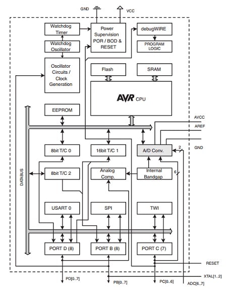
The ATmega328P microcontroller includes FLASH memory – 32kb for storing the program, RAM memory-2kb, EEPROM memory – 1kb, timers/counters – Two 8-bit & one 16-bit to count internal or external CLK cycle events & produces an interrupt once it reaches a particular count value. It also includes a 10-bit ADC with 6 channels, a Serial communications port, and an I2C interface port.

ATmega328P Microcontroller Architecture
To make the ATmega328P microcontroller function these connections should be made.
Power & GND
The 5 V power supply voltage must be given to pin 7 like VCC and also the GND connections are given on pins 8 & 22.
Memory
ATmega328P microcontroller includes three kinds of memories like flash, SRAM, and EEPROM.
Flash Memory (32KB): It is a PROM or programmable read-only memory and it is a nonvolatile memory.
SRAM (2KB): SRAM or static random access memory is a volatile memory. So once the power supply is removed then data will be removed.
EEPROM (1KB): EEPROM or electrically erasable programmable read-only memory. These are called byte erasable chips because it allows individual data bytes to be removed & reprogrammed. Generally, this memory is used for storing small amounts of data within computing and other electronic devices.
Registers
The ATmega328P microcontroller includes three general-purpose I/O registers GPIOR0, GPIOR1 & GPIOR2 which are used to store any data & are useful mainly to store status flags & global variables. The general purpose I/O registers within the address range from 0x00 to 0x1F are bit-accessible directly with the CBI, SBI, SBIC & SBIS & instructions.
Clock
The CLK signal must be given to the microcontroller in order to operate. The CLK signal comes from three different sources on the microcontroller. So, the clock source selection can be made within the chip by simply programming fuse bits.
A TTL-compatible CLK signal is externally generated through other logic & is given to pin 9 like XTAL1 of the microcontroller. On the other hand, the processor produces a CLK if a crystal is connected directly to the inputs of XTAL1 & XTAL2.
The third technique utilizes an internal oscillator that works at 8MHz approximately. So this is possibly the least accurate method to produce a clock. The main benefit of utilizing the internal CLK is that you do not require supplying any exterior signal.
In UART0 serial communications interface applications, the selection of CLK frequency simply devices the baud rates which can be used for transmitting & getting serial data. So, the baud rate frequency accuracy mainly depends on the CLK frequency utilized for the microcontroller.
Reset
To operate the microcontroller normally, the RESET pin should be high state.
SPI Programming
On the ATmega328P microcontroller, the Flash memory is simply programmed with connections to the RESET i/p & other three pins like PB3, PB4 & PB5. These pins are used for other purposes if the design lets the programming hardware include single access to these pins throughout the programming procedure.
I/O Pins
The microcontroller has 21 pins when utilized with an external CLK that can be arranged for general-purpose I/O. So, most of these pins can also be utilized for other purposes like timers, ADC, and many more. All the I/O pins can sink or source current to drive LEDs. For every port, there are mainly three registers that control the functions of the port’s individual bits like data direction, Port o/p, and Port i/p.
Timer/Counters
The ATmega328P contains three timers like Timer/Counter0, Timer/Counter1 & Timer/Counter2. These timers/counters allow you to control an external device at a specified time, generate a precision o/p signal like duty cycle, period & frequency, measure incoming digital signal characteristics, and also to count external events.
Serial Communications Interface
The ATmega328P includes USART which is used for interfacing the “COM” port on a PC. The transmission of data can be done on the TxD pin of the microcontroller and also received on the RxD pin. The transmitter & receiver of USART0 utilizes similar pins on the controller as I/O ports like PD0 & PD1. The baud rates to transmit & receive serial data can be derived simply from the main CLK that drives the microcontroller. The baud rate can be determined by the value within the Baud Rate Register and is determined by the below equation.
UBRR = (fosc/16 × BAUD) − 1
Where “fosc” is the CLK rate of the processor & BAUD is the preferred baud rate.
I2C Interface
The ATmega328P microcontroller is capable of communicating with other chips with the help of an I2C serial interface. I2C Interface is a 2-line bi-directional interface mainly designed for communication with medium speed between chips on a board. There are many ICs that have I2C interfaces like temperature sensors, EEPROMs, RAM, real-time-clocks, etc.
SPI Interface
The ATmega328P microcontroller includes a Serial Peripheral Interface module that allows communication through other devices with the SPI. This SPI protocol is a bidirectional serial interface that transmits data between different devices. The interface includes two data lines, MOSI, MISO & clock line. Additionally, the microcontroller should have extra enable lines to every SPI device it needs to commune with to decide which device is allowed for SPI data transfers.
A/D Conversion
The ATmega328P microcontroller includes an internal 10-bit ADC for changing analog voltage values to a binary. The ADC inputs are mainly used for different tasks such as voltage sampling to decide the position of an i/p control.
The ADC generates values from 0 to 1023 for input levels between GND & whatever higher reference voltage is chosen. The ADC accepts i/p from any one of six pins based on the bits within the control register. It performs only a conversion of single input at a time. The conversion procedure needs an internal CLK that can be produced from the microcontroller CLK by arranging a pre-scalar to separate it down to attain 50 kHz & 200 kHz frequencies.
Bluetooth & IR sensor Interfacing with ATmega328P Microcontroller
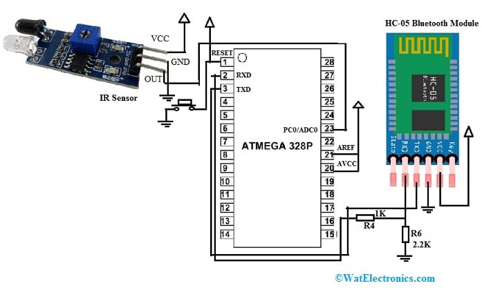
The Bluetooth module & IR sensor can be interfaced with ATmega328P Microcontroller to inform the operator remotely once the sensor detects any object. So this system is used mainly in the manufacturing industry, home automation & robotics projects. The best examples of this application are object counting, detection of alarms, and intrusion where the operator informs remotely.
The required components to make this interfacing mainly include the ATmega328p microcontroller, HC-05 Bluetooth module, and IR sensor. The connections of this interfacing follow as;
- The TXD & RXD pins of the Bluetooth module are connected directly to the TXD & RXD pins of the ATmega328 pins correspondingly.
- The Bluetooth module’s RXD is a 3.3Volts logic level pin thus two 1KOhm & 2.2KOhm resistors form a resistor divider that changes the logic level of the microcontroller from 5Volts to 3.3Volts.
- The Bluetooth module’s Vcc & GND pins are connected to the +5V & GND connections of the microcontroller.
- The out pin of the IR sensor is connected directly to pin-23 of the microcontroller.
- The sensor’s Vcc & GND pins are connected to the +5V & GND pins of the microcontroller.

Bluetooth & IR sensor Interfacing with ATmega328P Microcontroller
Code
The required code for Bluetooth communication & object detection through the IR sensor is shown below.
#include <avr/io.h>
#include <util/delay.h>
#define UBRRVAL 51 //9600 baud rate for 8MHz
void usart_init(void);
void sendbyte(unsigned char);
void sendstr(unsigned char *);
unsigned char defaultmsg[] = “Object Detected!:\n”;
int main()
{
DDRC &= ~(1<<PC0); //make PORTC pin 0 input for IR sensor
usart_init();
while(1)
{
while(PINC & (1<<PC0));
UCSR0B |= (1<<TXEN0);
sendstr(msg);
_delay_ms(3500);
UCSR0B &= ~(1<<TXEN0);
}
return 0;
}
void usart_init(void){
UBRR0H= (unsigned char)(UBRRVAL>>8); //high byte
UBRR0L=(unsigned char)UBRRVAL; //low byte
UCSR0B &= ~(1<<TXEN0);
UCSR0C |= (1<<UCSZ01)|(1<<UCSZ00); //Set data frame format: asynchronous mode,no parity, 1 stop bit, 8 bit size
}
void sendbyte(unsigned char MSG){
while((UCSR0A&(1<<UDRE0)) == 0); // Wait if a byte is being transmitted
UDR0 = MSG;
}
void sendstr(unsigned char *s){
unsigned char i = 0;
while(s[i] != ‘\0’){
sendbyte(s[i]);
i++;
}
}
Working
Whenever the infrared sensor detects any object, then it informs the microcontroller then the microcontroller sends a message like “object detected” to the mobile phone of the operator through a Bluetooth module. Here, ATmega328p USART is utilized for communicating through a mobile phone with a Bluetooth module.
Advantages & Disadvantages
The advantages of the ATmega328P microcontroller include the following.
- ATmega328P microcontroller has high performance.
- This microcontroller consumes less power.
- These are very simple to use.
- It is a stand-alone chip.
- These are affordable.
- It is readily usable with no extra computing components by 23 programmable I/O lines & 32KB of onboard flash program memory.
- It is code efficient and all registers are connected directly to the ALU to make it faster as compared to CISC microcontrollers.
The disadvantages of the ATmega328P microcontroller include the following.
- As compared to high-bit microcontrollers, these microcontrollers’ performance is slow.
- It is expensive when considering little tasks.
- This microcontroller includes 14 digital pins which are not used all in projects. Thus, resources will be wasted.
Applications
The applications of the ATmega328P microcontroller include the following.
- The ATmega328P microcontroller is used on different Arduino development platforms like Arduino uno, nano & micro boards.
- These microcontrollers are used in industrial control systems, SMPS & Power Regulation systems.
- It is used in digital data processing, autonomous systems, motor control systems, display units, and peripheral interface systems.
- It is used in different embedded systems like coffee machines & vending machines.
- It is used for analog signal measuring & manipulations.
- These are frequently used in various projects wherever a simple, low-cost & low-powered microcontroller is necessary.
Please refer to this link to know more about the ATmega328P microcontroller datasheet.
Thus, this is an overview of the ATmega328P Microcontroller, pin configuration, specifications, architecture, interfacing, and its applications. This is an AVR technology-based high performances microcontroller including a number of pins & also features. This controller is mainly designed with 8-bit CMOS technology & RSIC CPU that improves its power efficiency & also performance. This controller has internal protection & also various programming techniques so that the engineers give more priority to this controller to use in multiple applications. Since this microcontroller is used within Arduino boards, then you can change the Arduino board through this microcontroller directly by simply installing the Arduino bootloader into the IC. Here is a question for you, what is the advantage of using this microcontroller with an Arduino board?