The antenna is the most essential component of the radio equipment and the antennas were first developed by Heinrich Hertz in the year 1888. Later on, the antennas were developed to use for long-distance applications and wireless telegraphy. Moving on with the concept of antenna, Ferdinand Braun invented the concept of antenna array by placing three monopoles in the form of a triangle. So, let’s discuss more on the need for an antenna array, antenna array definition, radiation pattern, its gain, and a few examples.
What is Antenna Array?
Before moving to the detailed concept of an antenna array, let’s start by knowing the basics of the antenna array.
The name of the antenna array indicates that it is an array of antennas connected together to function as a single antenna that is employed for the transmission and reception of radio waves. It is also termed the radiating system that includes individual components (antennas) and radiators. Every radiator in the system that operates holds its specific induction field. The antennas that are in the system are so closely placed to one another that one antenna lies in the induction field of other antennas. So the radiation pattern of the system is considered to be the vector sum of all the individual antennas.
While placing the antennas in an array, the spacing between antennas should be proper and in exact phase which contributes that every antenna in a similar direction will be summed up thus forming a radiation beam and canceled in all the other directions. This type of arrangement enhances the directivity of the system. When all the antennas in a system are arranged in a straight line, it is termed a linear antenna array.
In addition, when all the components are excited with a similar magnitude of current which has a constantly accelerating phase shift all through the line, it is called a uniform linear array.
Antenna Array Working
In general, an antenna array functions using a half-wave dipole antenna. Whereas, the length is not exactly the same as a half-wave dipole and it varies by 5%.
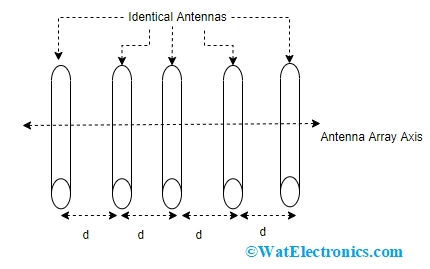
The below picture shows the antenna array architecture.

Antenna Array Architecture
As a half-wave dipole antenna has a radiation pattern of omnidirectional radiation, the waves radiated from the antenna array have a wider angle. Thus, to enhance the capability of those antennas and to radiate only in one particular direction, the antennas are arranged in an array pattern. So, various components are separately placed having exact spacing. Also, the components are concurrently excited through the current having an exact phase.
The current in different components is termed to be in the proper phase when it achieves high gain while flowing in the same direction and at the same time period. So, when the components are provided with the proper phase, the spherical waveform from every component of the array gets superimposed because of interference and makes a plane wave. This is considered the beam of a radio waves.
The interference can either be destructive or constructive that is based on the radiation of waves of all the components. When the radiated waves from the components are in the proper phase, then those are constructively added thus increasing the radiated power. Whereas when the radiated waves from the components are out of phase, then those are destructively added so that canceling out each other leads to a decrease in the radiated power.
Thus, the radiations from the components which are in phase deliver a directional beam that has more strength having the ability to travel longer distances.
Also, when the total number of components is increased, then the main lode becomes narrower and side lobes get smaller which corresponds to an increase in the antenna’s gain.
Below is the antenna array radiation pattern.
Types
Antenna array types are mainly categorized into four types which are explained as below:
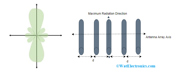
Broadside Type
In the broadside antenna array, similar elements are placed in a parallel way all across the line that is normal to the antenna’s axis. This is the widely employed antenna configuration and all the elements are positioned horizontally with similar spacing between them and every element in the array is provided with a current having a similar phase and magnitude levels. When there is excitation to the elements, then the array delivers maximum radiation in the normal direction of the antenna axis, whereas in the other directions less amount is delivered. This forms a bidirectional radiation pattern.

Broadside Type
The characteristics of the broadside type of antenna array are:
- The broadside array can vary between 2λ to 10λ.
- Employed mainly for overseas broadcasting systems and used for LF, HF, and ML frequency ranges.
- The total number of elements used in the array is based on spacing, price, and beamwidth necessity.
- When a broadside antenna array is operated along with a reflector, the directivity and gain of the antenna array in the broadside type can be increased.
End-Fire Type
The arrangement of elements in the end-fire type is the same as that of the broadside antenna array and the difference occurs in the excitation pattern provided to the end-fire antenna. Here, the elements are provided with 1800 out of phase. This type of arrangement delivers maximum radiation across all the array axis.
The end-fire antenna is excited with current having a similar magnitude level but has phase difference across the line thus creating a unidirectional radiation pattern. It is said that phase differences should vary corresponding to the progressive distance between elements.

End Fire Antenna Array
The characteristics of the end-fire type of antenna array are:
- The total number of elements used in the array is based on spacing, price, and beamwidth necessity.
- When a broadside antenna array is operated along with a reflector, gain and directivity can be increased.
- Employed mainly for overseas broadcasting systems and used for point-to-point communication purposes.
- The distance between the elements is either λ/4 or (3λ)/4.
- The total number of either dipoles or elements of the same size should be used.
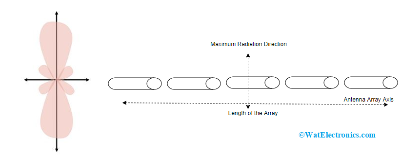
Collinear Type
The name of the antenna itself signifies that the arrangement of different elements is stacked in a single line. The line arrangement can be in the horizontal or vertical directions. The excitation is fed to every element in the antenna having a current with a similar phase and magnitude. The radiation pattern is in the normal direction to the antenna array axis. So, the collinear antenna arrays’ major lobe provides a circular symmetry pattern that enables an omnidirectional radiation pattern.
When the elements are placed at a distance of 0.3 to 0.5λ between them, the array offers maximum gain whereas this directs to constructional and feeding issues. In order to avoid those problems, the elements are closely placed. The directivity of the antenna gets increased when the array length is increased.

Collinear Type
The characteristics of the collinear type of antenna array are:
- A collinear array with two elements is widely used because it supports multi-band functionality.
- Few of the applications employ the combination of collinear, end-fire, and broadside types of antennas as this enhances the directivity and gain to the maximum extent.
- A collinear array with 4 elements is not practically employed as it does not deliver the required amount of power gain.
Parasitic Type
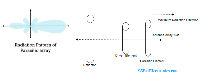
These are the multi-element type of antenna arrays delivering maximum gain and directivity. Even without providing excitation to every element in the array, it assists in solving feedline issues. Here, the fundamental operation is feeding a few of the elements in a parasitic arrangement. In the parasitic type antenna array, the excitation is provided only for the driven element whereas the rest of the elements are parasitically excited.

Parasitic Type
The elements which are fed in a direct approach are termed parasitic elements and these receive power from the radiation released from the driven component which is close to it. This is called electromagnetic coupling.
The current developed in the parasitic element because of the driven component is based on the distance (mostly λ/4 and a 900 phase difference) that is present in between two elements together with the tuning. The parasitic array radiation pattern is the outcome of the reflector which is behind the driven component adding back-reflected signals with the forward wave.
Antenna Array Solved Problems
1). In a uniform linear type antenna array, the spacing between four isotropic radiating elements is considered as λ/4. Find the progressive phase shift (α) between the elements in order to form the major lobe at 600 off the end-fire?
Here, the normalizer effector is
(AF)normalizer = sin 4 (ψ/2)/ 4 sin (ψ/2)
Ψ is considered as total phase difference
Ψ = α + β dcosθ
- Ψ = α + (2π/λ) (λ/4) cos 600
- 0 = α + (π/2 ) (1/2)
- α = -(π/4) radians
- In an antenna, the far-field magnetic field component is as follows:
H’ϕ = 1/r [sqrt (sinθcosϕ/30π)] A/m where 0<θ<π and θ<ϕ<π/2. Find the antenna’s directivity.
Wrad = ½ |E’ * H’| = ή/2 |H’|2
- (ήsinθcosϕ)/2r2 * 30π
- U = r2Wrad = (ή/60π) sinθcosϕ = U0sinθcosϕ
- Prad = sinθdθdϕ
- Prad = U0sin2θcosϕdθdϕ
- Prad = U0 * π/2
- D = (4πU0)/(Prad) = 9.04 dB
Advantages and Disadvantages
Here are the antenna array’s advantages and disadvantages.
Advantages
- With an antenna array, one can achieve maximum directivity and gain.
- A maximum level of SNR ratio and good performance can be obtained.
- Minimum power wastage
- To the great extent, minor lobes are reduced.
- Increased signal strength.
Disadvantages
- The maintenance of the antenna array is complex.
- To set up this system, more outer space is needed.
- The system shows high resistive losses.
Antenna Array Applications
A few of the applications of the antenna array are:
- Antenna array finds crucial applications in the communication domain.
- Employed in military radar systems.
- Mostly used for long-distance communications.
- Satellite and wireless transmissions.
- Used in astronomical observations.
How does an antenna array work?
An antenna array uses multiple antennas to capture and transmit signals in different directions. The directionality of the antennas can be adjusted to focus on a particular direction or zone. Using this method, an antenna array can collect information from multiple sources at once and send it to a central point or multiple points. This makes them ideal for use in military applications where there may be many targets in different locations that need monitoring simultaneously.
Know more about Yagi Uda Antenna MCQs & Antenna MCQs.
Why do we need an antenna array?
We need an antenna array to increase the range and quality of our signal.
What are some common types of antenna arrays?
There are two main types of antenna arrays: phased and non-phased. Phased arrays have a number of elements that are connected together with their phases shifted by a specific amount. Non-phasers have elements that are connected together directly in a single path, with no phase shift between them.
Why is an antenna array better than a single antenna?
An antenna array is a group of antennas that are physically close together and can be used to send or receive electromagnetic waves. The individual antennas are connected to each other, which allows the signal from one antenna to be transferred to another. This allows for the creation of systems that are more effective than if they were made up of only one antenna.
This is all about an overview of an antenna array. Here, we have clearly discussed antenna array working, how radiation pattern is achieved, types, applications, and advantages. Here is a question for you, what is the radiation pattern?