In the scope of electrical engineering, we are familiar with resistance in digital circuits. Along with this, impedance also shows the impact in AC circuits where consists of the consequences of both capacitance and inductance. The impedance generated by these consequences is combinedly stated as reactance and this creates the imaginary part of the complex impedance while resistance creates the real part. The reciprocal term of impedance is admittance. The inventor of the term admittance is Oliver Heaviside in the year 1887. This article clearly explains the concept of admittance, its formula, how the derivation is done, series and parallel circuit and some related concepts.
What is Admittance?
Admittance is utilized for measuring the allowing ability of the current through a device or circuit. This is the inverse of impedance which is similar to how conductance is related to resistance. The SI admittance unit is Siemens and represented by the symbol S. To know clearly about the concept of admittance, let us initially consider its related topics.
We are aware that resistance has no phase but has magnitude and this is the term that calculates the amount of opposing current flow. Coming to the analog circuit, along with the resistance there are two other scenarios that are to be observed and those are capacitance and inductance. Because of this, impedance comes into action where these have similar functionality like resistance but consists of both phase and magnitude values. The real value is the resistance, and the imaginary value is reactance.
As admittance functions opposite of impedance, it can be stated that is calculates the amount of current flow that is permitted by a circuit or device. Admittance also calculates the dynamic consequences of the substance’s susceptance towards polarization, and this is calculated in Mho or Siemens.
Derivation
As we have already discussed that impedance includes both real and imaginary parts which are termed as resistance and reactance and the symbol for impedance is ‘Z’ and the admittance symbol is ‘Y’ symbol. This is represented as
Z = R + jX
Where ‘Z’ indicates Impedance and is measured in Ohms.
‘X’ indicates Reactance and is measured in Ohms.
‘R’ indicates Resistance and is measured in Ohms.
With the definition, it is
Y = 1/Z = Z-1 which is 1/(R + jX)
So, Y = [1/(R2 + X2)] (R – jX)
Admittance is like impedance is a complex number that has conductance (G) as real part and susceptance (B) as imaginary part.
Y = G + jB
Here ‘Y’ represents admittance and is measure in Siemens
‘G’ represents conductance and is measure in Siemens that implies R/(R2 + X2)
‘Y’ represents susceptance and is measure in Siemens that implies – [R/(R2 + X2)]
Here, the negative sign is in the case of capacitive susceptance and positive sign for inductive susceptance.
j2 = -1
|Y| = sqrt(G2 + B2) = 1/(sqrt(R2 + X2))
Angle(Y) = arctan (B/G) = arctan (-X/R)
This is how derivation of admittance from impedance is done.
Admittance Triangle
In the same way as the impedance triangle, the admittance triangle is also represented. As the circuit’s impedance consists of rectangular components which are reactance and resistance. In the same way, admittance also consists of two components which are susceptance and conductance.
The below picture shows the admittance triangle.
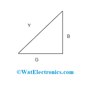
Admittance Triangle
Admittance Relay
The admittance relay is also called high-speed or Mho relay. Here, the functional torque is achieved by the volt-amperes factor and the controlling component is generated because of the voltage component. This specifies that the admittance relay is a voltage-managed directional relay. The schematic diagram consisting of the induction cup is shown below:
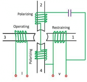
Admittance Relay
The functional torque is generated by the collaboration of fluxes because the poles 2, 3, and 4 and managed torque is generated because of poles 1, 2, and 4.
When the spring managing effect is represented by -K3, then the torque equation is shown as:
T = k1VI cos(ϴ – 900) – K3
Here, ϴ and T are indicated with a positive sign when the I lags V. And at the equilibrium position,, the net torque equals zero and so the equation is
K1VI cos (ϴ – T) – k2V2 – K3 = 0
(K1/K2) cos (ϴ – T) – (K3/K2VI) = V/I = Z
Z = (K1/K2) cos (ϴ – T)
When the spring managed effect is not taken into consideration, then K3 becomes zero that is K3 = 0
Series Circuit Admittance
Case 1: When a circuit is included with resistance, inductance, and reactance in series connection it is shown as below: This is represented as follows:
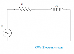
Series Connection with R and L
Y = 1/Z = Z-1 = 1/(R + jXL)
This is the basic admittance formula.
Where XL = inductive reactance measured in ohms
Y = [1/( R + jXL)] * [(R – jXL)/( R – jXL)] = (R – jXL)/( R2 + XL2)
Y = [R/( R2 + XL2)] – j[XL /( R2 + XL2] = G – jBL = sqrt(G2 + BL2)
Where BL indicates inductive susceptance measured in Mhos.
Case 2: When a circuit is included with resistance, capacitance, and reactance in series connection it is shown as below: This is represented as follows:
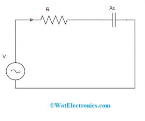
Series Connection with R and C
Y = 1/Z = Z-1 = 1/(R – jXC)
Where XC = capciatance reactance measured in ohms
Y = [1/( R + jXC)] * [(R + jXC)/( R + jXC)] = (R + jXC)/( R2 + XC2)
Y = [R/( R2 + XC2)] + j[XC /( R2 + XC2] = G + JBC = sqrt(G2 + BC2)
Where BC indicates capacitive susceptance measured in Mhos
This is the admittance of a series circuit.
Parallel Circuit Admittance
A circuit included with two branches’ names ad branch A and branch B is displayed in the below picture. Branch ‘A’ consists of inductive reactance represented as XL and resistance whereas branch ‘B’ consists of capacitive reactance XC and resistance. A supply voltage of ‘V’ is provided to the circuit.
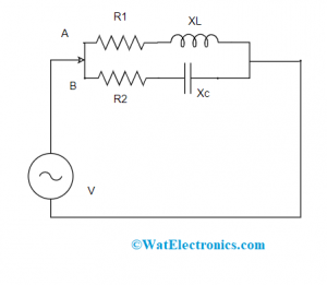
Admittance of Parallel Circuit
For branch ‘A’
G1 = [R1/R12 + XL2]
Where G1 indicates conductance and Z1 indicates impedance measured in Ohms
Inductive susceptance BL = R1/(R12 + XL2) = R1/Z12
Admittance Y1 = G1 – jBL = R1/Z12 – j(XL/Z12)
For branch ‘B’
G2 = [R2/R22 + XC2] = R2/Z22
Where G2 indicates conductance and Z2 indicates impedance measured in Ohms
Inductive susceptance BC = XC/(R22 + XC2) = XC/ZC2
Admittance Y2 = G2 + jBC = R2/Z22 + j(XC/Z22)
Total Admittance is given by Y = Y1 + Y2
Y = G1 – jBL + G2 + jBC = (G1 + G2) – j(BL – BC)
= [(R1/Z12) + ( R2/Z22)] – j [(XL/Z12) – (XC/Z22)]
So, for a parallel circuit, the total admittance is given by
Y = sqrt[{[(R1/Z12) + ( R2/Z22)]2} + {[(XL/Z12) – (XC/Z22)]2}]
Total Current, I = VY
And the power factor, cosφ = G/Y = (G1 + G2)/Y
With this, it can be known that when a circuit’s admittance is known, then the entire power factor and current can be known.
This is all about the concept of Admittance. Here, the article has provided a clear description of admittance definition, its triangle, admittance in series and parallel circuits, and related information. Furthermore, it is more required to know about how admittance is used in real-time applications?