In the industrial sector, the measurement of water or gas flow is a very significant process for controlling different processes as well as for the machinery for the best levels of performance & efficiency. So, flow can be defined as the volume (or) area for each unit time at which point a substance moves throughout a specified cross-section & is characterized at precise pressures & temperatures. The sensor used to measure flow is known as a flow sensor. So, flow measurement is crucial in different industries like chemical & petroleum. This article discusses an overview of a flow sensor – working with applications.
What is a Flow Sensor?
A flow sensor definition is a sensor that is used to measure a fluid like liquid or gas. These sensors mainly use both electrical and mechanical subsystems to gauge changes within the physical attributes of fluid & measure its flow. So measuring these mainly depends on the physical attributes of fluid. A flow sensor is an electronic device that measures the changes in liquids flow rate & gasses in tubes & pipes.
The flow sensor working principle is based on Bernoulli’s principle. This principle states that the drop of pressure across the meter is simply proportional to the square of the rate of flow. The most common way to determine the measurement of a flow is by using the pressure drop across the cross-section of the pipe.
Flow Sensor Types
Flow sensors are categorized into three types like the following.
- Positive displacement flow sensors.
- Mass flow sensors.
- Velocity flow sensors.
Positive Displacement Sensor
These types of flow sensors are very unique as compared to other types because they measure the fluid’s volume directly when passing through the device. Other types of flow sensors do not measure the rate of flow directly instead of measuring pressure, it is used to derive the flow rate.
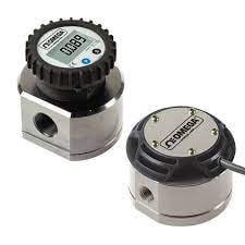
Positive Displacement Flow Sensor
In this kind of sensor, the volume of known fluid is trapped & moved throughout the rotary parts. It turns the components & once it completes a complete revolution, then it is guessed as the volume of known fluid supplied throughout the sensor. Counting the revolutions which occur for each unit time setups the fluid volume supplied for each unit time. As the flow of fluid moves the components directly, then rotating velocity is proportional directly to the rate of flow.
These flow sensors can work over a broad range of fluid viscosities; they have less maintenance & provide an electronic & mechanical interface. These sensors are used in the measurement of gasoline, oils, hydraulic liquid, and water and gas meters installed at home.
Mass Flow Sensor
A mass flow sensor measures the flow rate of fluid or the amount of fluid or gas flowing throughout a pipe by simply determining the mass for each unit of time. These sensors are extensively used in automobiles, wherever they are utilized to measure the air inflowing the air intake system of an inside combustion engine. They work by simply measuring the energy transfer from a heated surface to a flowing liquid. These sensors are also available in two types thermal & Coriolis flowmeter.
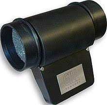
Mass Flow Sensor
The advantages of this sensor are; liquid flow can be measured directly with high accuracy, applicable for an extensive range of fluids like highly viscous fluids, and flow measurement can be done bidirectionally.
Velocity Flow Sensor
Velocity flow sensors are used for detecting the liquid flow speed by simply determining the fluid’s velocity flowing throughout the sensor. These kinds of sensors are available in different types like mechanical, electromagnetic & ultrasonic which are discussed below.
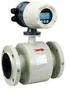
Velocity Flow Sensor
Mechanical Velocity Flow Sensor
In a mechanical velocity flow sensor, a rotary mechanical device like a paddle wheel is arranged on a bearing that extends from the flow sensor & directly sits within the flow path. When the fluid moves, the paddle wheel rotates & its rotation is simply detected by a sensor like an infrared sensor, magnetic coil, or Hall effect. The flow sensor electronics converts the revolutions into an o/p signal like a rectangular wave signal that can be simply programmed to signify a specified volume output for each unit time.
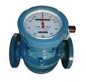
The advantages of these flow sensors are compact, expensive with a simple working principle & also use very small energy to function. These sensors work with a broad range of fluids. The main drawbacks are; this sensor uses moving parts that may build up contagion from liquids that are not hygienic so that its operation can be obstructed & needs maintenance.
Electromagnetic Flow Sensor
Sometimes, these flow sensors are also known as magnetic flow/ EMF flow sensors which operate on Faraday’s law of induction principle. These sensors mainly include a coil that induces a magnetic field within the liquid being measured and after that, it uses a set of electrodes to determine the induced voltage that results from the conductive liquid flow throughout the magnetic field.
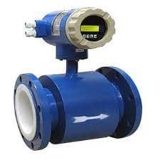
Electromagnetic Type
The induced voltage is proportional to the fluid’s velocity within the pipe. The measurement of velocity is changed into a volumetric flow rate if we know the velocity & dimensions of the cross-section of the pipe.
These sensors mainly need that the liquid being measured to have the least conductivity and have the benefit of not inducing a pressure drop within the pipe. Whenever they are appropriate for fluids that contain some amount of contamination, then they do not work with non-conductive fluids such as steam, gas, or oil. These types of flow sensors are not suitable to use within vacuum conditions, the fluids which have abrasive characteristics & fluids that may contain ferromagnetic particles.
Ultrasonic Flow Sensor
These sensors use two different approaches to work. In the primary approach, an ultrasonic transducer pair produces a signal that is simply directed into the fluid flow from two locations. Every signal produced by a transmitter can be simply reflected back to the other transducer’s receiver with a set of mirrors. The direction of the transducers & mirrors is; one signal is transmitted through its path by the flow of fluid whereas the other is transmitted against the flow of fluid.
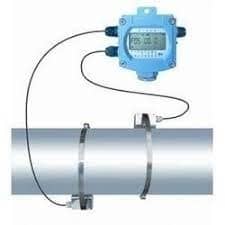
Ultrasonic Type
The receiver electronics simply measure each signal’s transit time & measures the time variation between the two. Once the fluid is not in movement, then transit times are similar for every signal. When the fluid is in motion, then the signal moves with the fluid flow which will have less transit time, so the variation between the two transit times of the signal reflects the fluid’s velocity. Sometimes, these kinds of sensors are called transit time ultrasonic flow sensors.
In a second approach, ultrasonic force is simply transmitted into the liquid & is reproduced back to a receiver. In the zero-flow state, the ultrasonic wave frequency is not changed. Once the fluid is in motion, then there is a change in frequency that simply occurs as an outcome of the Doppler Effect. This effect is linear with respect to the velocity of the fluid. So, detecting & reporting the shift within ultrasonic frequency simply allows for the calculation of the flow rate of the fluid. These sensors are applicable for both conductive & non-conductive liquids and they can handle high pressures & temperatures.
Flow Sensor Vs Pressure Sensor
The differences between the flow sensor and the pressure sensor include the following.
| Flow Sensor | Pressure Sensor |
| The flow sensor is used to detect the flow rate of fluids. | The pressure sensor is used to detect the pressure of fluids and gases. |
| These sensors are available in three types Positive displacement, mass flow & velocity flow. | These sensors are available in seven types strain gauge, piezoelectric, capacitive, manometer, vacuum, bourdon, and aneroid. |
| This sensor is most commonly known as a flow meter. | A pressure sensor is alternatively known as pressure transmitters, transducers, senders, indicators, manometers & piezometers |
| These are normally used in medical devices, chemical factories, HVAC systems, etc. | This sensor is used in many medical, automotive, consumer, building devices, and industries that depend on stable & precise pressure measurements to function consistently. |
Flow Sensor Interfacing with Microcontroller/Flow Sensor with Arduino
The flow sensor interfacing with the microcontroller is discussed below. Here, the flow sensor used is YF-S201 with any type of microcontrollers like Arduino, Pic microcontroller, STM32 Blue Pill, ESP32, 8051 microcontrollers, ESP8266, or Raspberry Pi for measuring water flow rate.
Monitoring water flow is very significant in different applications such as a watering system for plants within your home garden and food processing & complex pharmaceutical industries. So water flow sensors help in measuring the liquid flow rate where the flow rate is the volume of water supplies throughout a sensor for each unit of time.
There are different types of water flow sensors available and these sensors are nearly similar except for the variation in the range of flow rate, length, operating range of voltage, material, and size but their interfacing and working principle process will be the same.
YF-S201 water flow sensor is mainly designed for measuring the water flow rate & amount of the required fluid throughout the pipes. This sensor is available at a low cost and includes a copper body as well as a water rotor. Additionally, it also includes an internal Hall effect sensor circuit that functions on the electromagnetism principle & provides signals at the o/p pin. This sensor is compatible with MCU with 30 liters for each minute maximum flow rate.
YF-S201 Flow Sensor Pin Configuration
The Pin configuration of the YF-S201 flow sensor is shown below. This sensor includes three pins and each pin and its functionality is discussed below.
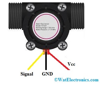
YF-S201 Flow Sensor Pinout
- Pin1 (RED): This is a positive (+) supply wire.
- Pin2 (BLACK): This is a negative (-) supply wire.
- Pin3 (YELLOW): This is an o/p voltage wire.
Features & Specifications
The features and specifications of the YF-S201 flow sensor include the following.
- The operating voltage of this sensor ranges from 5 to 24 V.
- Normal voltage ranges from 5V to 18 V.
- The maximum current is 15 mA at 5V.
- The capacity of the load is ≤10 mA Volts at 5V.
- The capacity of flow rate is 1 to 30 Liters per min.
- Electric strength is 1250 V/min.
- Range of water pressure is ≤ 1.75 MPa
- The operating temperature is ≤ 800C.
- The operating liquid temperature is ≤ 1200C.
- The range of humidity is 35% to 90% RH.
- Insulation resistance is ≥ 100 Mohms.
Generally, a water flow sensor includes a turbine wheel or water rotor and a hall effect sensor. The water enters through one of the ends & leaves from another end of the sensor. Once water is supplied through this sensor, then it hits the wheel of the turbine & rotates the turbine wheel. The turbine’s speed has a direct relation to the rate of the water flow throughout the water flow sensor. On every complete revolution of the wheel of the turbine, a hall-effect sensor generates a pulse that emerges on the signal o/p pin. So, the number of appeared pulses on the signal o/p pin is directly proportional to the turbine’s rotating speed.
YF-S201 is made with a plastic body that includes a rotor, valve & a Hall effect sensor. These sensors work on the principle of the Hall effect & generate the flow rate & volume in the pulses form on the signal pin.
The below section shows how to interface the YF-S201 Water Flow Sensor with an Arduino Uno . It can be interface with the other microcontroller as well the same way but pins only need to be changed.
Interfacing of the YF-S201 Water Flow Sensor with an Arduino Uno microcontroller
Connection Diagram
In this example, we will use digital I/O pin-2 of Arduino as an external interrupt capture pin to count the number of pulses.
Connect the YF-S201 water sensor’s power supply pins to the GND & Arduino’s 5V pins.
The yellow color wire (o/p voltage wire) to the Arduino’s ‘D2’ digital pin to detect the electric pulses.
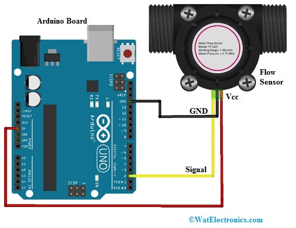
Flow Sensor Interfacing with Arduino
Code
This Arduino interfacing with the water flow sensor simply measures the flow rate of water in units of a liter for each hour & displays the measured value on the Arduino IDE serial monitor.
/*YF- S201 water Flow sensor code for Arduino */
const int Output_Pin = 2;
volatile int Pulse_Count;
unsigned int Liter_per_hour;
unsigned long Current_Time, Loop_Time;
void setup()
{
pinMode(Output_Pin, INPUT);
Serial.begin(9600);
attachInterrupt(0, Detect_Rising_Edge, RISING);
Current_Time = millis();
Loop_Time = Current_Time;
}
void loop ()
{
Current_Time = millis();
if(Current_Time >= (Loop_Time + 1000))
{
Loop_Time = Current_Time;
Liter_per_hour = (Pulse_Count * 60 / 7.5);
Pulse_Count = 0;
Serial.print(Liter_per_hour, DEC);
Serial.println(” Liter/hour”);
}
}
void Detect_Rising_Edge ()
{
Pulse_Count++;
}
To test the above interfacing, copy the above Arduino code to Arduino IDE & upload it to your Arduino board. Later, open the serial monitor & set the baud rate to 9600. So, we can notice the measured values over the serial monitor:
The o/p of this project is to show the amount of water supplied throughout the sensor within liters for each hour. To get this, there is a calculation. Since the sensor’s output is a pulse, so by calculating the pulse frequency, we can simply measure the amount of water supplied throughout the sensor. The frequency of pulse within Hz is 7.5 * Water Flow Rate in Litres for each minute. Thus, the water quantity in Litres for each Hour is Pulse Frequency x 60 / 7.5.
Advantages
The advantages of flow sensors include the following.
- Response time is very fast.
- Small mass flow rates.
- Detection of the direction of flow.
- Power consumption is low.
- Thermal mass is small.
- Its design is robust.
- The performance ratio of price is best.
- Less maintenance although still simple to maintain.
- No extra pressure drop.
Disadvantages
The disadvantages of flow sensors include the following.
- It is used for only liquids/gases.
- Not suitable for highly contaminated liquids.
- Gas bubbles can cause errors.
- These sensors are vibration sensitive when not properly installed.
- Installation cost & its maintenance is high.
- Prone to corrosion through water-based fluids
- Expensive due to its complex design.Needs very clean fluid.
- Low-density liquids cannot measure.
Applications
The applications of flow sensors include the following.
- The flow sensor is used to measure the amount of liquid flowing throughout it. So this can be utilized in many industrial & commercial applications.
- This sensor is mainly used for indicating the amount of fluid or gas moving throughout a pipe or medium by measuring mass, linear, volumetric, and non-linear flow rates.
- Generally, these types of sensors are commonly used in medical devices, HVAC systems, septic systems & chemical factories. These sensors are capable of detecting blockages, leaks, pipe bursts & changes within a concentration of liquid because of pollution or contamination.
- These sensors are used in automobiles to gauge the air intake to the engine & regulate the delivery to fuel injectors in order to attain the mixture of desired fuel to the engine.
- These sensors are used in medical ventilators to establish the correct rate of delivery of air otherwise oxygen to patients for support through respiration.
Know more about Pulse Sensor, PIR Sensor.
Thus, this is all about an overview of a flow sensor – working with applications. Here is a question for you, what is an air sensor?