Magnetic sensors are the sensors that convert the change/ magnitude of a magnetic field into an electrical signal. The Earth’s magnetic field or the magnetic field referred to as magnetism, is a well-known but invisible phenomenon. Magnetic sensors convert invisible magnetic fields into electrical signals and help to have visible effects. They were designed decades ago as a sensor using the electromagnetic induction effect and has expanded into applications in the magneto-resistance effect, galvano-magnetic effect, the Josephson effect, and other physical phenomena. This article gives a brief description of working, types, and interfacing of a magnetic sensor.
Magnetic Sensor Definition
Magnetic sensors are the solid state devices used in detecting and sensing the distance, speed, rotation, angle, and position by converting magnetic information into electrical signals. The converted signals are processed by electrical circuits. These sensors became popular and used in several applications because of their easy operation, and tolerance to high vibrations, water, and dust.

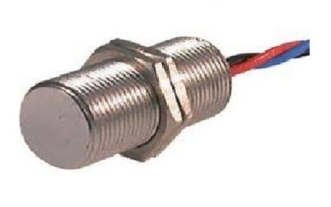
Magnetic Sensor
These are used to detect the strength of the magnetic field and geo-magnetism generated due to the current or magnet. The output of the magnetic sensors is used to monitor the direction, location, revolution, angle, distance, speed, position, and the presence of electric current. The magnetic sensors can detect the linear and rotatory motion of small iron objects without any external power supply with high resolution. They can measure up to 6,00,000 rpm speed.
These are high-frequency sensors and the frequency usage can be limited by the impedance and the external load. Magnetic field type sensors use an internal magnet or permanent magnet to detect electromagnetic fields directly. The built-in magnetic sensor detects iron and generates an analog or digital output signal. Reed switches, Hall switches, and other external magnetic sensors detect the magnetic field of a magnet or electric coil. Also available in analog and digital versions.
Magnetic Sensor Working Principle
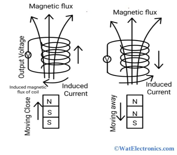
The magnetic sensor working principle is based on the type of sensor element used. Any type of magnetic sensor works with the magnetic field of the Earth. A simple magnetic sensor can detect the moving ferrous. When an iron object is moved close to the coil Or wire wound on a permanent magnet, then the magnetic flux through the coil changes and generates the voltage at the terminals of the coil.

Working Principle Magnetic Sensor
Consider the coiled magnetic sensor, where the coil is used as a simple sensor element to understand the working of a magnetic sensor. However, the coil is used to provide limited functionality. So, it is combined with other magnetic materials coils, to construct a highly sensitive magnetic sensor. The coils used in magnetic sensors in a wide range of applications include fluxgate sensors, search coils, resolvers, rotation, and angle sensors.
The coil itself can’t be used to measure magnetic fields directly, but it can detect changes or vibrations in the magnetic field. When the magnet is brought closer to the coil, the coil’s magnetic flux density will increase. This results in creating the opposite forces in the form of an induced current and electromotive force (EMF). When the movement of the coil stops, the change in the magnetic flux density also stops, and the induced EMF and current stop.
Observe the induced EMF and the induced current, to determine the ratio of the change in density and direction of the magnetic flux.
Types of Magnetic Sensors
The magnetic sensors are divided into various types based on the technology or elements used such as fluxgates, coils, hall elements, light pumping, magnetoresistive, nuclear precession, SQUID, magnetic tunnel junctions, giant magnetic impedance, piezoelectric component, optical fibers, small electro-mechanical elements, etc. The different types of magnetic sensors are given below.
Magnetoresistive type Magnetic Sensors
These sensors are used to measure electrical resistance as a function of the applied magnetic field. It works on the principle of AMR (Anisotropic magneto-resistance) or MR (Magneto-resistance) or GMR (giant magneto-resistive) or TMR (tunnel magneto-resistive) effect developed by William Thomson in 1856, Albert Feet & Peter Grunberg in 1988 and Terunobu Miyazaki professor in 1995.
Hall Effect Magnetic Sensors
These are used to convert the stored energy in a field of the magnet into an electrical signal with the application of a voltage between the ends of a current-carrying wire whose sides are 90 degrees to the magnetic field. It works on the principle of the Hall effect developed by Edwin H in 1879.
Fluxgate or Coiled type Magnetic Sensor
These sensors are used to measure the magnetic field difference at the vertical rod ends and then display this data on a grid.
Magnetic Induction type Sensor
This sensor contains a coil surrounding a ferromagnetic core, the permeability of which varies with the earth’s magnetic field of the Earth.
Overhauser Magnetic Sensors
These sensors are also called nuclear precession type sensors that combine a liquid electron-rich with hydrogen and expose the mixture to an RF signal.
Precession Proton Magnetic Sensors
These sensors utilize liquids such as methanol, and kerosene with hydrogen atoms having high density.
SQUID Magnetic Sensors
In SQUID Magnetic Sensors, the term “SQUID” stands for Superconducting Quantum Interference Devices which are used to measure magnetic fields in a very low femto Tesla range. These are sensitive type sensors and are used in medical, and neuroscientific, applications with several magnetic field devices.
Optically Pumped Magnetic Sensor
An optically pumped magnetic sensor polarizes an alkaline gas with light with a particular wavelength.
Magnetic Sensor Interfacing with Microcontroller using Arduino UNO
From the above information about magnetic sensors, now let’s know how to interface a magnetic sensor with a microcontroller (ATMEGA328P) using Arduino UNO. Here the Hall effect magnetic sensor in the form of A1104 IC is taken.
Pin Diagram Of Magnetic Sensor:
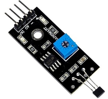
The hall effect magnetic sensor is the most widely used magnetic sensor in various applications such as door open and close detection, docking detection, proximity sensing, pulse counting, valve positioning, automotive systems, etc. The pin diagram of the hall effect magnetic sensor module is shown below.

Magnetic Sensor Module Pin Configuration
Pin 1:VCC (+): This pin refers to the supply pin, which is used to supply the power to the module.
Pin 2: GND (-): This pin refers to the common ground connection.
Pin 3: AO: (Analog Out): This pin refers to the analog output, which is connected to the analog pin of the microcontroller directly.
Pin 4: DO: (Digital Out): This pin refers to the digital output, which is connected to the digital pin of the microcontroller directly.
Now let’s know briefly about A1004 Hall effect magnetic sensor IC.

Magnetic Sensor Interfacing
Hall sensor ICs are magnetically activated non-contact trigger switches used in various applications such as computers, security systems, automobiles, control systems, and many more. The Hall effect IC A1104 is from Allegro MicroSystems, available in 3-pin SOT23 and SIP packages. It is based on BiCMOS technology, which combines the advantages of the technologies of bipolar and CMOS.
The main components of the A1104 Hall Effect magnetic sensor IC are a voltage regulator, a Hall effect sensor, a low power signal amplifier, a Schmitt trigger, and an output NMOS transistor. It is used to detect the moment, change, and position in the strength of the magnetic field of either an electromagnetic or permanent magnet or ferromagnetic materials.
The Hall effect chip A1104 has 3 pins: VCC, GND, and OUT.
- VCC: Provides a positive power supply to the chip from 3.8V to 24V.
- GND: Ground connection
- OUT: IC output pin.
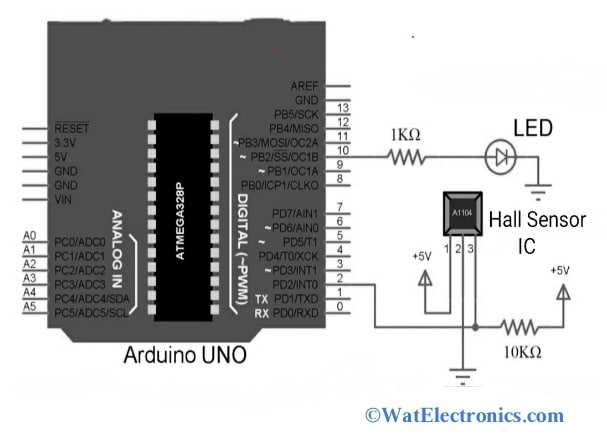
The circuit diagram of interfacing the Hall effect magnetic sensor with the microcontroller using Arduino UNO is shown below. The components required are,
- Hall-effect magnetic sensor IC A1104.
- Arduino UNO board.
- Resistors of 10kiloOhms and 1kiloOhm.
- LED.
- Breadboard.
- Connecting wires.
Connections are made as per the above circuit diagram. The VCC and GND pins of A1104 are connected to +5V and GND pins of Arduino UNO. The OUT pin or Hall pin of A1104 is pulled to HIGH with a resistor of 10 Kilo Ohms and connected to digital pin 2 of Arduino. To represent the output LED is connected to digital pin 10 of Arduino through a resistor of 1kiloOhms.
When a magnetic field is applied near to the Hall Effect A1104 IC, the output pin (OUT) of the Hall effect magnetic sensor IC goes LOW. This change is recognized by the Arduino and activates the corresponding LED.
Upload the Arduino code and observe the results on the monitor.
Arduino Code:
const int ledPin = 10;
const int hallPin = 2;
volatile bool ledState = LOW;
void setup()
{
pinMode(ledPin,OUTPUT);
pinMode(hallPin,INPUT);
attachInterrupt(digitalPinToInterrupt(hallPin), hall_ISR, CHANGE);
}
void loop()
{
digitalWrite(ledPin, ledState);
}
void hall_ISR()
{
ledState = !ledState;
}
Examples of Magnetic Sensors
Magnetic sensors convert magnetic fields into electrical signals. Examples of magnetic sensors are considered based on direct and indirect applications.
In a direct application, the magnetic pickup is part of the magnetometer. Examples include measuring geomagnetic fields, reading magnetic storage media, recognizing magnetic patterns on cards and banknotes, and controlling magnetic devices. In indirect applications, a magnetic field is used as an intermediate medium to detect non-magnetic signals.
Examples include floating current detection for overload protection, built-in power meters, and non-contact detection of linear or angular position, displacement, or speed detection using permanent magnets. These applications require magnetic field measurements in the range of micro- and millitesla, which can be achieved with embedded solid-state sensors.
Magnetic induction will be the measure for solid-state magnetic sensors such as magnets.
B= μµ oH
Where B= magnetic induction measured in Tesla or Vs/m².
H= vector of magnetic field
µ o= permeability of free space.
µ= relative permeability.
Advantages
The following are the few magnetic sensor advantages.
- Easy to operate with non-contact wear.
- Small size
- Maintenance is easy
- Robust in design
- The magnetic lines of force are not blocked or interrupted by aluminum, plastic, copper, or any other non-magnetic materials.
- They can detect the properties of moving objects.
Disadvantages
A few disadvantages of magnetic sensors are,
- They are not applicable to measuring the flow of current greater than the distance of 10cm.
- The magnetic sensing capability is affected by the high temperature.
Magnetic Sensor Applications
The following are the applications of magnetic sensors.
- Automobile and Automotives
- Robotics and factory automation
- Military
- Biomedical applications
- Geophysics applications
- Industrial measurements
- Space equipment
- Consumer electronics
- Agriculture
- Power supply units
- Water and energy appliances
- Green energy power plants
Thus, this is all about an overview of a magnetic sensor and its types. The magnetic sensors are influenced by the moment of charge carriers and sensitivity of sensor elements and technologies such as hall elements, MR elements, AMR elements, GMR elements, optical cables, and other electronic components. The hall effect sensors are the most widely used magnet sensors in various applications such as automotive, robotics, industrial, etc.