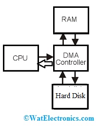
To execute any operation in a computer system, first, the microprocessor gets the instruction, decodes it, and further, executes. However, if the microprocessor is executing the entire task individually within the system, then it keeps the microprocessor busy continually. Therefore, to improve the processor’s performance, an external device like a DMA controller is utilized to control the operation of data transfer between memory & peripherals with the least utilization of CPU.
Basically, it is hardware-controlled data transfer; wherever both the address & control signals necessary for the data transfer are produced by the DMA controller. So this article discusses an overview of DMA controllers – working with applications.
What is DMA Controller?
DMA controller definition is, an external device that is used to control the data transfer between memory and I/O device without the processor involvement is known DMA controller. This controller has the capacity to access the memory directly to read or write operations. DMA controller was implemented by Intel for having very fast data transfer with less utilization of the processor.
How Does DMA Controller Work?
The direct memory access controller produces memory addresses and it covers numerous hardware registers that can be read & written through the CPU. These registers mainly include a byte count, memory address & minimum of one or above control registers. So based on the DMA controller features, these registers can select some combination of source, destination, transfer direction, the transfer unit size & the number of bytes to move within the single burst.

DMA Controller
To execute different operations like input (i/p), output (o/p), otherwise memory-to-memory, the host processor initializes the controller by the number of words to transmit & the memory address to utilize, then the CPU orders the peripheral device to start data transfer.
The DMA controller provides addresses & reads or writes control lines toward the system memory. Every time, a data byte is arranged to be transmitted in between the memory & peripheral device, the controller increases its inside address register until a whole data block is transmitted.
Data transmission in DMA controller:
The data transmission in the DMA controller can be done in three modes like burst mode, cycle stealing mode, and transparent mode.
Burst Mode
In this mode, the transmission of a complete data block can be done in a continuous series. When the CPU permits the direct memory access controller to access the system bus, then this controller will transmit all data bytes within the data block before releasing the system control buses back to the CPU, although it will cause the CPU to be not active for a long time. So this mode is also known as Block Transfer Mode.
Cycle Stealing Mode
The cycle stealing mode is mainly used in a system wherever the CPU cannot be stopped for the time taken for the burst transfer mode. In this type of mode, the direct memory access controller gets the access to the system bus by using the Bus Grant & Bus Request signals. These signals are similar to the burst mode which mainly controls the interface between the DMA controller & the CPU. In this mode, the speed of data block transmission is not fast as compared in burst mode, however, the idle time of the CPU is not as long as within the burst mode.
Transparent Mode
This mode uses more time for transmitting data blocks; however, it is also the most significant type of mode in the overall performance of the system. In this mode, the DMA controller transmits data simply whenever the CPU executes operations that do not utilize the buses of the system.
The main benefit of this mode is that the CPU never ends performing its programs & DMA transmits are free in terms of time, whereas the drawback is that the hardware requires to decide once the CPU is not utilizing the buses of the system, which can be complex. So this is also known as hidden DMA data transfer mode.
DMA Controller Types
There are three types of DMA controllers like third-party DMA, first-party DMA, and bus master DMA which are discussed below.
Third-party DMA
This type of DMA uses an engine of system DMA, which includes different DMA channels obtainable to utilize through I/O devices. The device mainly depends on the DMA engine of a system to achieve the transfer of data between the memory & I/O device. The driver utilizes the engine routines of DMA to initialize as well as program the engine of DMA. For data transfer of every DMA, the DMA engine can be programmed by the driver and after that gives the device a signal to start the transfer jointly with that engine.
First-party DMA
In this type of direct memory access, the device can drive its own DMA bus cycles through a channel from the DMA engine of the system. The function of ddi_dmae_1stparty is mainly used to arrange this channel within a cascade mode so that the engine of direct memory access (DMA) will not interfere with the transfer.
Bus-Master DMA
If the device acts as a true bus master then the driver must program the DMA registers of the device directly. So the transfer address & count are attained from the cookie of direct memory access & set to the device.
DMA Controller Architecture
The DMA controller block diagram has four channels that can be used over four input/output devices and each channel consists of a 16-bit address and 14-bit counters. Each channel in the DMA controller is programmed independently and they transfer the data up to 64kb.
The direct memory access controller is used only for transferring the data, it doesn’t do any modifications, so it reads, writes the data, and verifies the transfer data. The DMA controller operates in two modes they are master mode and slave mode. Whenever the CPU sends the acknowledgment to the DMA controller it acts as master mode, similarly whenever the CPU didn’t send the acknowledgment to the DMA controller then up to that point it acts as a slave.

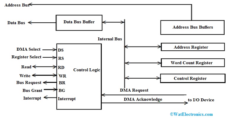
DMA Controller Architecture
The lines that are provided between input/output devices and the control logic is DMA request and DMA acknowledges. Whenever the input-output device is ready to transfer, then the CPU will initiate the DMA, so in the initiation, process CPU will give an address from where the data has to be written or read.
Word count and control register: The word count is also provided by the CPU, so in the initiation process the count of how many words are read and written can be done by the CPU. The control register consists of the control signals whether that is a read signal or a write signal. The CPU will load the address, count, and control registers through the data bus.
Bus request, register select, and DMA select: To select the device the DMA select control is used, the register select control is used to select the registers. The CPU will have the bus request pin, so the request sent by the DMA to the CPU states that the DMA asking for the bus to access.
Bus Grant: The content in the bus grant is sent by the CPU, the CPU will also have the bus grant pin, so the bus grant states that permission is granted to access the bus and that will be decided by the CPU. So, after the permission is granted the control signal will send by the CPU to the direct memory access unit. If the bus grant is high that means input/output device content can be transferred to the memory.
Interrupt: This pin is used whenever the input/output device wants to access the memory, so the interrupt is forwarded to the DMA and that interrupt access is again forwarded to the CPU.
Address bus and Data bus: The address that is there in the address register is forwarded through the address bus line and the data that needs to be transferred will be forwarded through the data bus line.
Difference between I/O Program Controlled Transfer vs DMA Transfer
|
I/O Program Controlled Transfer |
DMA Transfer |
| The data transfer can be controlled through software. | The data transfer can be controlled through hardware. |
| The speed of data transfer is slow. | The speed of data transfer is very fast. |
| While transferring data, the CPU involves. | The CPU is not involved while transferring data. |
| Additional hardware is required. | For transferring data, a DMA controller is necessary. |
| It is used for small data transfer. | It is used for large data transfer. |
DMA Controller Verilog Code
// DMA Top module
module Dma8237aTop(dma_if.DUT dif);
// DMA interface instantiation
DmaControlIf cif(dif.CLK, dif.RESET);
DmaRegIf rif(dif.CLK, dif.RESET);
// DMA modules instantiation
// Datapath module
DmaDatapath D1(dif, cif, rif);
// Timing and Control module
DmaTimingControl C1(dif, cif, rif);
// Priority logic
DmaPriority P1(dif, cif, rif);
Endmodule;
Advantages and Disadvantages
The advantages of the DMA controller include the following,
- It allows a peripheral device to read or write from memory without using the CPU.
- DMA controller increases the operations of the memory by avoiding CPU involvement.
- It reduces the overload work on the CPU.
- For every transfer, simply a few clock cycles are necessary.
- DMA decreases the required clock cycle to read/write a block of data.
- The disadvantages of the DMA controller include the following.
- DMA controller-based systems are expensive.
- Cache coherence troubles can occur while using DMA for transferring data.
- System price can be increased.
Applications
The applications of DMA controller include the following,
- A DMA controller is used to generate memory addresses & begin memory read/write cycles.
- The process of transmitting data without the processor’s involvement is frequently used for transmitting data from input to output devices.
- This is a hardware device used to allow I/O devices to access memory directly with less involvement of the processor.
- The data transmission can be done at the fastest rate by using DMA.
- The DMA device performs like a bus master to read & write physical memory.
- This device is mainly used to offload the software & processors from copying large data from one place to another within memory
Know more about Control Unit MCQs.
Thus, this is all about an overview of a DMA controller – working with applications. This is one type of hardware device used to allow I/O devices to access memory directly with low participation of the processor. This controller requires the similar old circuits of an interface to converse with the Input/Out. This controller includes three registers address, word, and control. Here is a question for you, what is a microprocessor?