Ultrasonic sensors are in available for the past many decades and these devices continue to hold huge space in the sensing market because of their specifications, affordability, and flexibility. As the automation industry has been progressing, the employment of ultrasonic sensors in multiple domains such as drones, EV vehicles is emerging. In the year 1914, Fessenden developed the first modern transducer employed in sonar where it can be able to find the items in water but not the direction of items. And then in the year, 1915 Langevin introduced the contemporary model of ultrasonic which resolved the problem of Fessenden. ultrasonic sensor definition, how it works, it’s specifications, its integration with Arduino, and its advantages are explained clearly in this article.
What is Ultrasonic Sensor?
Ultrasonic sensors are electronic devices that calculate the target’s distance by emission of ultrasonic sound waves and convert those waves into electrical signals. The speed of emitted ultrasonic waves traveling speed is faster than the audible sound.
There are mainly two essential elements which are the transmitter and receiver. Using the piezoelectric crystals, the transmitter generates sound, and from there it travels to the target and gets back to the receiver component.
To know the distance between the target and the sensor, the sensor calculates the amount of time required for sound emission to travel from transmitter to receiver. The calculation is done as follows:
D = 1/2 T * C
Where ‘T’ corresponds to time measured in seconds
‘C’ corresponds to sound speed = 343 measured in mts/sec
Ultrasonic sensor working principle is either similar to sonar or radar which evaluates the target/object attributes by understanding the received echoes from sound/radio waves correspondingly. These sensors produce high-frequency sound waves and analyze the echo which is received from the sensor. The sensors measure the time interval between transmitted and received echoes so that the distance to the target is known.
Ultrasonic Sensor Specifications
Knowing the specifications of an ultrasonic sensor helps in understanding the reliable approximations of distance measurements.
- The sensing range lies between 40 cm to 300 cm.
- The response time is between 50 milliseconds to 200 milliseconds.
- The Beam angle is around 50.
- It operates within the voltage range of 20 VDC to 30 VDC
- Preciseness is ±5%
- The frequency of the ultrasound wave is 120 kHz
- Resolution is 1mm
- The voltage of sensor output is between 0 VDC – 10 VDC
- The ultrasonic sensor weight nearly 150 grams
- Ambient temperature is -250C to +700C
- The target dimensions to measure maximum distance is 5 cm × 5 cm
Ultrasonic Sensor Arduino
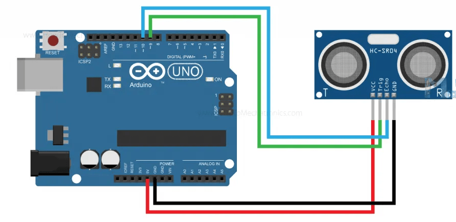
This section explains the interfacing of the ultrasonic sensor with an Arduino by considering HC-SR-04 where it explains the ultrasonic sensor pinout, its specifications, wiring diagram, and how the sensor with Arduino connection.
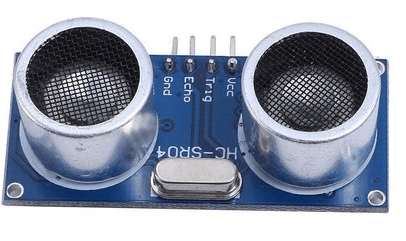
The ultrasonic sensor pin diagram is:

Ultrasonic Sensor Pin Diagram
Vcc – This pin has to be connected to a power supply +5V.
TRIG – This pin is used to receive controlling signals from the Arduino board. This is the triggering input pin of the sensor
ECHO – This pin is used for sending signals to the Arduino board where the Arduino calculates the pulse duration to know the distance. This pin is the ECHO output of the sensor.
GND – This pin has to be connected to the ground.
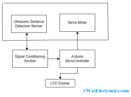
The below picture shows the ultrasonic sensor block diagram for distance measurement.

Ultrasonic Sensor Block Diagram
The target’s distance is calculated using an ultrasonic distance sensor and the output from the sensor is provided to the signal conditioning section and then is processed using an Arduino microcontroller. The results from the microcontroller are fed to the LCD display and then moved to a personal computer.
The ultrasonic sensor can be connected to the servo motor to know the polar distance of the sensor up to 1800 rotations approximately.
Working
In general, an ultrasonic sensor has two sections which are the transmitter and receiver. These sections are closely placed so that the sound travel in a straight line from the transmitter to the target and travels back to the receiver. Making sure to have minimal distance between transmitter and receiver section delivers minimal errors while calculations.
These devices are also termed ultrasonic transceivers because both the transmitter and receiver sections are combined in a single unit which considerably minimizes the PCB footprint.
Here, the sensor operates as a burst signal and it is transmitted for some period. Later the transmission, there exists a silent period and this period is termed response time. The response time indicates that it is waiting for the reflected waves.
The shape of the acoustic waves that leave the transmitter section resembles the same shape of the light emitted from a laser so beam angle and spread have to be measured. When the sound waves move away from the transmitter, the detection area increases vertically and sideways too. Because of the varying detection area, the coverage specification is considered either as beam angle/beamwidth other than the standard area of detection.
It is more recommended to observe the beam angle pattern for the sensor whether it is the complete angle of the beam or the angle of variation corresponding to the straight line that forms a transducer. Mostly, a thin beam angle results in a higher detection range, and a broader beam angle corresponds to a lesser detection range.
The transmitted/acoustic signals might find a hindrance or not. When there is any hindrance, the acoustic wave bounces back from the hindrance. This bounced signal is termed ECHO. This echo travels to the receiver.
Then the received signal is either filtered or amplified and then transformed into a digital signal. With the time between transmission and reception of acoustic waves, the distance between the ultrasonic system and hindrance can be known.
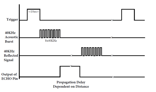
Let us consider an example to know the Ultrasonic sensor timing diagram.
Consider HC-SR-04 ultrasonic sensor where we should provide trigger pulse. It produces a sound wave with a frequency of 40 kHz (corresponds to 8 pulses). This makes the ECHO pin to the HIGH state. The echo pin will stay in a HIGH state until and unless it receives the ECHO sound. Therefore, the echo pin width is calculated as the time for the sound to travel from an object and get back. From the time, the distance is measured and this is termed sound speed.
The rangeability of HC-SR-04 is 2 cm – 400 cm.
The below picture shows the timing diagram of HC-SR-04.

Ultrasonic Sensor Timing Diagram
Procedure to analyze the timing diagram:
- To the Trig pin, the trigger pulse should be supplied for at least 10 µsec.
- Then the device automatically transmits eight pulses of 40 kHz and waits for the rising edge to appear on the output pin.
- When the echo pin observed a rising edge, start the timer and observe the time required to appear falling edge at the echo pin.
- When the echo pin shows a falling edge, observe the timer count. The count of the timer indicates the time taken by the sensor for object detection and getting back from the object.
As we know that
D = S * T
D = Distance
S = Speed
T = Time
Total distance is measured as = (343* Time at HIGH ECHO)/2
Note: ‘343’ in the above formula indicates the sound speed in air medium considered at room temperature.
The total distance is divided by 2 because the sound wave travels from the source to the object and then returns back to the source.
The code for ultrasonic sensor with Arduino is explained as follows:
Code to Measure Distance
//defining pin numbers
int trig = 9; // trigger pin connected to 9th pin in Arduino board
int echo = 8; // echo pin connected to 10th pin in Arduino board
// defining variables
long timetaken;
int distance;
void setup() {
pinMode (trig, OUTPUT); // sets the trigger pin as output mode
pinMode(echo, INPUT); // sets the echo pin as input mode
// initiating the serial communication
Serial.begin(9600);
}
Void loop () {
digitalWrite (trig, LOW); // clearing the trigger pin
delayMS (2);
digitalWrite (trig, HIGH); // sets the trigger pin to HIGH state for 10 µsec
delayMS (10);
digitalWrite (trig, LOW);
timetaken = pulseIN(echo, HIGH); // calculates the time taken by pulse from echo pin
distance = timetaken * 0.034/2; // measures the distance
serial.print (“Timetaken:….”) // prints the value on LCD display
serial.println(timetaken);
}
Code to Filter Noise in Ultrasonic Sensor
The result measured from the ultrasonic sensor comes with noise. In most situations, the noisy output causes unnecessary functionality in the device and shows errors too. The noise can be filtered out from output through the below approach.
- Try with multiple calculations (consider 2 trails) and sort the result in an array.
- Sort the stored array in ascending format.
- Filter the noise levels (the smallest and biggest 5 samples are termed to be noise and we can ignore those)
- Observe the average value of middle sample from 5th trial to 14th trial
int trig = 9;
int echo = 8;
float filter_Array[20]; // defining array to store multiple data sample received from the sensor
float distance; // stores the distance from ultrasonic sensor
long timetaken;
int distance;
void setup() {
pinMode (trig, OUTPUT);
pinMode(echo, INPUT);
}
Void loop(); {
for (int trial =0, trial < 20; trial++) {
filter_Array[trial] = ultrasonicMeasure();
delay(30); // to eliminate
}
// initiating the serial communication
Serial.begin(9600);
}
void loop () {
digitalWrite (trig, LOW); // clearing the trigger pin
delayMS (2);
digitalWrite (trig, HIGH); // sets the trigger pin to HIGH state for 10 µsec
delayMS (10);
digitalWrite (trig, LOW);
timetaken = pulseIN(echo, HIGH); // calculates the time taken by pulse from echo pin
distance = timetaken * 0.034/2; // measures the distance
serial.print (“Timetaken:….”) // prints the value on LCD display
serial.println(timetaken);
}
The above explains the functionality of the ultrasonic sensor with Arduino.
Factors Influencing Ultrasonic Sensor
A radar cross-section helps to know how well a target holds the ability to reflect ultrasonic waves and transmit them back. Slanting/curved objects scatter most of the ultrasonic signals those are transmitted towards the target and result in minimal echo response. Whereas the surfaces like smooth, flat, dense, and large provide strong echo responses.
Minor targets or targets that moderately deflect sound such as human beings, animals and plants result in minimal sensing responses. In order to generate a higher sensing response, a flat target should be towards the sensor at a 900 angle. But, rigid/rough surfaces show larger angular deviations.
The below picture shows the reflection pattern of ultrasonic waves depending on the shape of the target.

Reflection Pattern As Per The Target Shape
Advantages and Disadvantages of Ultrasonic Sensor
In most of the domains, ultrasonic sensors are widely employed because of their advantages which are as follows:
Advantages
- These devices are not impacted by the target’s color.
- The device shows flexibility in its distance measurement range where it holds the capability of measuring in the range of a few centimeters to five meters.
- It provides consistent outcomes and shows high reliability.
- High precision device.
- The measurements can be made every second thus showing rapid refresh rates.
Disadvantages
Even though ultrasonic sensors employ versatile technology, there are a few limitations to be considered and those are:
- As sound speed is based on humidity and temperature, environmental circumstances might show an impact on the accuracy while measuring the distance.
- For minimal and embedded projects, ultrasonic sensors seem to be a not good option because these devices are large to integrate with small projects.
- These sensors will not function in a vacuum.
- The sensors will get dirt, wet and frozen which results in errors while measuring or the functionality gets impacted.
Applications
The applications of ultrasonic sensors are:
- Used in robotic sensing for positioning of robotic arms.
- Employed in washdown design for constantly noticing the filling level of objects on a conveyor belt.
- Used to detect objects.
- The diameter of the coil/roll can be known by ultrasonic sensors.
- Used to avoid a collision.
- Proximity detection.
know more about PCB Design MCQs.
Know more about MB1240 Ultrasonic Sensor Datasheet.
Where are ultrasonic sensors used?
The primary usage of ultrasonic sensors is proximity sensors where we can find these sensors in the anti-collision safeguarding domain and vehicle self-parking technologies.
What is the range of the ultrasonic sensors?
The operating frequency range of ultrasonic sensors is between 30 kHz – 500 kHz.
Can ultrasonic waves hurt humans?
When there is a long time of exposure to ultrasound waves, it results in symptoms such as headache, dizziness, and a few hearing problems. People can come across these symptoms when the ultrasound wave’s frequency crosses 20 kHz.
What can an Ultrasonic sensor detect?
Ultrasonic sensors are used for the detection of distance for an extended range of targets irrespective of the target’s surface, color, and shape.
This is all the concept of ultrasonic sensors. Here the article has explained the ultrasonic sensor working principle, its specifications, integration with Arduino, and its applications. Know how the ultrasonic sensor gained prominence in IoT?
