Over a century ago two men independently invented the Yagi-Uda antenna. Ever heard of it? Neither had we before we started looking at the history of the invention. Invented in 1926 by Shintaro Uda of Tohoku Imperial University and Hidetsugu Yagi, Kiyoshi Kawakami, and other colleagues at the same university, it was the first antenna designed to exploit the advantage of receiving signals from multiple directions to cancel out noise or jamming with high gain, high directionality, and uninterrupted line of sight. The pair Yagi and Uda became to be known as “the fathers of the antennas”. This article clearly explains on basics of yagi uda antenna, its design considerations, components, and applications.
What is Yagi Uda Antenna?
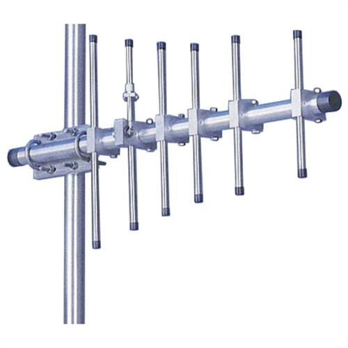
Yagi Uda antenna is also termed as Yagi antenna which is a directional antenna that has either two or more parallel resonant antenna components acting as half-wave dipoles. This antenna is majorly formed by three components which are reflector, driven element, and directors, where the single driven component has a connection either with the transmitter/receiver via a transmission line or other parasitic components. In general, the parasitic elements are the reflector and a number of directors(longer element).
These parasitic elements(shorter elements) are not electrically connected to the transmitter or receiver but instead act as passive resonators, working in conjunction with the driven element.
Yagi antennas are generally constructed to function in HF and UHF ranges and they provide the functional frequency between 30 MegaHertz to 3 GigaHertz, even when the bandwidth is very minimal. These antennas are uniquely designed to have good gain values which are more than 10dB.
Components
There are mainly three basic components of Yagi antenna which are:

Yagi Uda Antenna
Driven element – The driven element provides the necessary current required for radiating electromagnetic energy into space and is usually the same length as a half wavelength at the intended operating frequency. All other elements are electrical multiples of half a wavelength long so that they resonate at the same frequency as the driven element. The extra length or multiple of half wavelengths is achieved by inserting an inductance or capacitance into each parasitic element, which has the effect of increasing their electrical length without changing their physical length.
Reflector – The length of the reflector is generally 5% more than the driven element. Mostly, each Yagi Uda antenna consists of one reflector element which is at the back of the driven element which means at the sideways from where the maximum sensitivity happens.
Also, reflectors that are at the back of the driven element show no observable difference to the performance of the antenna. Whereas some designs employ reflectors with a reflecting plate or a sequence of parallel rods that resemble a reflecting plate. With this, there will be minimal increment in the device performance thus lessening the radiation level. Furthermore, this design pattern reduces the range of interference.
In general, a reflector adds approximately 4 – 5dB of gain in the forward path.
Director – Even when there is a single director or more directors, the length of directors is shorter than the driven component. The positioning of directors will be in front of the driven component which means in a direction that has a high level of sensitivity.
Mostly, there will be a gain of 1 dB across each director element in the forward path even though this level gets decreased when there are more directors.
The number of directors determines how many lobes appear on the radiation pattern of this antenna. The more lobes there are, the narrower they become, which means that they can focus on one particular direction.
Yagi Uda Antenna Working & Construction
This section explains the yagi uda antenna design and how it is operated.
Yagi Antenna Design
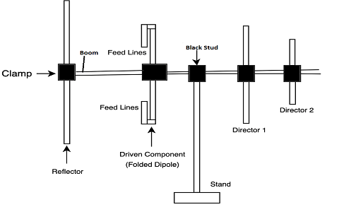
Yagi uda antennas were mostly observed on the roof of every house in past decades. The parasitic components and dipoles collectively form a yagi uda antenna. In the below picture, the antenna has more directors because placing more directors enhances the antenna’s directionality. The feeder is considered a folded dipole and the reflector has more length which is placed at the end of the antenna. Below picture shows the yagi uda antenna design diagram.

Yagi Uda Antenna Structure
In the design of the Yagi antenna, the structure which is in the form of a center rod where the components are placed is termed a boom. The active component is called a driven component where a transmission line has an internal connection to it through a black stud. The single material which is at the back end of the driven component is called a reflector where it reflects the entire energy in the direction of the radiation pattern. And the other components that are present before the driven component are called directors which reflect the beam in the direction of the required angle.
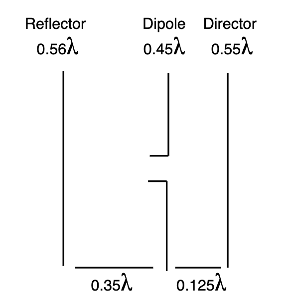
In order to design a Yagi antenna, there are a few parameters to be considered which are:
- Driven component length – 0.458λ to 0.5λ
- Reflector length – 0.55λ – 0.58λ
- Director 1 length – 0.45λ
- Director 2 length – 0.40λ
- Director 3 length – 0.35λ
- Distance between the directors – 0.2λ
- Spacing between reflector to dipole – 0.35λ
- Spacing from dipole to director – 0.125λ
When the above-mentioned design parameters of the yagi uda antenna are met, one can easily construct it.

The yagi uda antenna design equations are as follows:
All the below equations are corespondent to frequency and so for a 106Mh frequency
Driven component length = 143/f = 1.35 Mts
- Director 1 length = 138/f = 1.30 Mts
- Reflector length = 150/f = 1.41 Mts
- Director 2 length = 134/f = 1.26 Mts
- Boom length = (43/f) + (45/f) + (45/f) = 1.25 Mts
Working
Before getting into the operation of the Yagi antenna let us see how an antenna works?
Antennas are the devices that receive and send signals. When the incoming signal reaches the input terminal of the antenna, an alternating current is produced across its terminals in response to the incoming waves. This alternating current is coupled with the input terminal of the receiver through a coaxial cable or waveguide. In short, the receiver antenna receives electromagnetic waves and converts them into electrical signals, while the transmitter antenna converts electrical signals into electromagnetic waves.
Antennas have various shapes and sizes, depending on the specific application. In a typical antenna design, the conductor is usually bent into one or more geometric shapes such as a horizontal dipole or a folded dipole.
In Yagi-Uda antenna is mostly a folded dipole antenna. When an extrinsic excitation is supplied to the dipole. The current flow across the active component creates a voltage across parasitic components which makes the flow of current across it.
The component with more length than the wavelength/2 shows inductive characteristics so that the current in the reflector component lags the induced voltage. On the other hand, the short length component (director) induces capacitive characteristics so that the current flow across the director leads the induced voltage.
Yagi Antenna Transmission
As the positioning of the director is in the front place of the driven component, then the director adds the driven component field in its opposite direction (away from it). When there are multiple directors, then every director provides excitation to its subsequent one and so on. And, the reflector adds the driven component field in its own direction (close to it). This happens to minimize the losses because of the backward radiated signal. To achieve additional gain, it is recommended to employ more directors in the beam direction.
Fundamentally, the induced voltage and current flow because of induced voltage across the component differ with respect to the distance that is between parasitic and active components together with the reactance phenomenon related to the components.
The thing that has to be observed here is, that in the operation of the yagi uda antenna when the spacing between the director and driven component increases, then the necessity for capacitive reactance increases so that precise and correct phasing is provided at the director. Therefore, the director component’s length is maintained small to achieve capacitive reactance.
On the whole, it is understood that excitation to driven components is supplied through feed lines which allow for radiation emission from the reflector in the direction of the director. Also, this radiation emission induces the parasitic components which again re-radiates the radiations. So, the component’s length and their spacing hold more prominence due to the reason that radiation emitted from every component gets added in the front path and then cancels the backward radiated wave.
Please refer to this link to know more about Horn Antenna MCQs, Yagi Uda Antenna MCQs
Radiation Format of Yagi Antenna
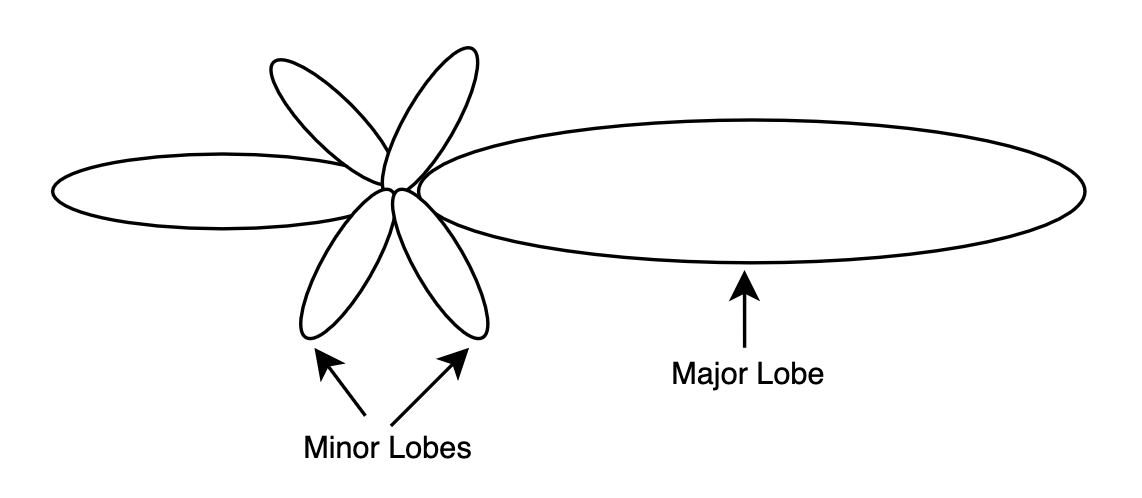
The radiation pattern of the Yagi antenna is highly directive and it is shown below:
In this radiation pattern, the major lobe corresponds to the forward radiated wave and there are many minor lobes at the rear and sideways. The foremost minor lobe is the reverse one that happened by the radiation in the reflector’s direction.

Radiation Pattern of Yagi Antenna
There is a chance of antenna optimization so that it minimizes the radiation in the reverse path. This happens by varying the length and distance of the reflector or it can also be optimized to generate a high level of forwarding gain. But, there is no perfect coincidence for the above scenarios which makes a person compromise on the performance of the antenna based on the application. So, it is required to select either a high level of front-to-back ratio or else more forward gain.
Characteristics & Application of Yagi Uda Antenna
This section explains the detailed characteristics and uses of the yagi antenna.
Characteristics
- A yagi antenna is termed a beam antenna when it has an array of only three components are reflector, one director, and a driven component.
- The antenna provides moderate directivity in one direction.
- The gain level provided by the yagi antenna is nearly 8 dB having front to back ratio of 20 dB.
- When there is a requirement to enhance the directivity, one can add more components to the array.
- Yagi antenna is also called a super-directive antenna because of its maximum directive gain.
- This is a frequency-sensitive device.
- In order to achieve a high level of impedance to have exact sync between free space and transmitter, one can use folded dipole as a substitute for the driven component.
- The resonant frequency of reflectors is low and directors are high when compared with that of driven component.
Yagi Uda Antenna Advantages
- The yagi antenna provides high gain.
- As directors are used, it has high directional features.
- These antennas are power efficient.
- The construction and maintenance are not complex.
- Pricing is not expensive.
- It has a good level of suitability for high-frequency activities.
Yagi Uda Antenna Disadvantages
- To achieve high gains with the yagi uda antenna, the antenna becomes more lengthy.
- Gain level limits to 20 dB for a single antenna or else the device becomes too large and beamwidth gets minimized.
- The antenna is prone to noise, interference, and atmospheric conditions so the performance of the device gets reduced.
Applications
A few of the applications of the Yagi antenna are:
- Yagi UDA antennas are employed in TV signal reception as this antenna holds good receiving capability.
- Used in defense applications.
- Employed in the astronomical domain.
- Also used in radio astronomy.
- What is a Yagi antenna used for?
A yagi antenna is used to establish short-distance communication in the range of 3 to 5 miles between two ends.
- How can I increase my Yagi Uda antenna?
When the gain of the antenna increases, then the length of the yagi uda antenna increases.
- At what range of frequency is the Yagi Uda antenna usually used?
In general, the frequency range of the yagi antenna is 3MHz to 300 GHz.
- What are the different elements of Yagi Uda antenna?
The main elements in the antenna are the director, reflector, and driven component (usually a folded dipole).
- Does an outdoor antenna need to be grounded?
All the outdoor antennas are to be grounded.
- Why are beverage antenna not used as transmitting antenna?
Beverage antennas do not hold much efficiency and so transmission becomes so complicated.
- what is the radiation pattern of a yagi-uda antenna?
It is the end-fire radiation pattern where the main lobe is in a parallel direction to the axis of antenna.
- What kind of antenna is Yagi Uda?
A yagi antenna is a directional antenna.
So, this is the whole concept of Yagi Uda antenna. This article has provided an idea of the yagi uda antenna working, its basics, construction, radiation pattern, and applications. Know how the tuning process in the yagi uda antenna can be achieved?