A Rectifier is said to be center tapped if it can rectify both the positive and the negative halves of the cycle. By using a transformer with a presence of wire at the secondary winding it makes the transformer center tapped. This is the reason it is termed as a Center Tapped Full Wave Rectifier.
The reason behind using this type of transformer is that it can utilize both halves of the cycle by connecting two diodes respectively. Compare to half-wave rectifier center tapped full wave has greater efficiency.
What is a Center Tapped Full Wave Rectifier?
A rectifier that utilizes both the cycles during rectification is said to be a full wave rectifier. If the rectification is done by the usage of the center tapped transformer in the full wave. It is said to be a center tapped full wave rectifier.
Full Wave Center Tapped Rectifier Circuit
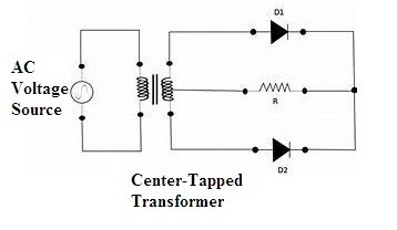
A full wave rectifier based on center tap consists of two diodes in it as well as a center tapped transformer along with that a resistive load is connected across it.

Full Wave Center Tapped Rectifier Circuit Diagram
Hence the connections as per the above circuit diagram as made in order to form a center tapped full wave rectifier circuitry. The wire at the center separates the respective cycles for both the diodes functioning during respective halves.
Full Wave Center Tapped Transformer Working
- The concept of additional wire has been introduced in this type of transformer. The connections of the wire have been found in the middle of the secondary winding.
- The functionality is remaining the same as that of the normal transformer it can be preferred for increment or decrement in the voltage levels.
- Another important point is to be noted here is that the applied input of alternating current (AC) is divided so that it can make the two diodes function during both the halves.
- As the secondary winding is concerned the upper half above the center tapped is representing the positive half of the cycle. The remaining part deals with the negative half of the cycle.
- However, the final generated output will always represent that the flow of current will be in a unified direction.
Full Wave Center Tapped Rectifier Working
- As the input applied to the circuit it gets equally split at the center that is positive half and the negative half.
- For the positive half, the upper part of the diode will be in forward bias that is in conducting mode. Hence a path is established so that the current flows in the circuit.
- Whereas for the first half the other diode in the lower part will be in reverse bias. Hence it is unable to conduct.
- In the above case, the direct current (DC) is observed across the load due to the first diode D1.
- For the next half of the cycle, the diode D1 will be in reverse bias. So there is no evident flow of the current.
- But D2 will be in the forward bias mode that makes the conduction possible for the negative half of the cycle.
- So the rectified output at the load is observed across the load is because of the diode D2.
- Hence the current at the load can be calculated based on the sum of the flow of the individual currents across the respective diodes.
- Hence both the cycles are utilized and the output after rectification is obtained it must be in the form of DC.
- But rectified output will always contain some ripples in it. In order to obtain the purest form of DC, the rectified output must be connected to the filter circuit.
- These filters can be either capacitors or inductors.
- The output generated in this type of circuit is recognized to be double of that of the half wave rectifier output. Hence this increases the efficiency of the circuit.
Output Waveforms
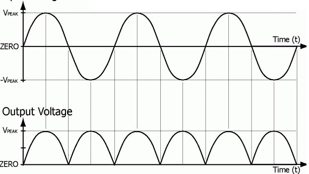
The output generated for the center tapped rectifier can be as follows

Center Tapped Rectifier Output Waveforms
It is evident that there is the presence of output for both the positive and the negative halves of the cycle. Hence no loss of cycle here and there is any loss in the output power as well. But finally generated outputs across the load will not be in its purest form of DC.
Equations
There are certain characteristics of the center tapped full wave rectifier. They are
(1) Ripple Factor
The output generated consists of a certain amount of ripples in it. These are measured in terms of the ripple factor.
The equation of the ripple factor can be given as
[latexpage]
\[
γ=√((V_rms/V_DC )^2-1)
\]
(2) Efficiency
It can be defined as the ratio between the generated DC output power to the applied input power in terms of AC.
[latexpage]
\[
E=(P_(DC ) output)/(P_AC input)
\]
(3) Peak Inverse Voltage
The amount of the voltage that can be able to withstand the diode during reverse bias condition is referred to as peak inverse voltage.
[latexpage]
\[
PIV=2V_s max
\]
The above are some of the equations of the center tapped rectifier.
Advantages
Some of the advantages of the center tapped rectifier are as follows
- The circuit is more efficient compared to that of half wave rectifier.
- There is no loss in power because both the cycles are utilized during rectification.
- The amount of ripples at the output generated is minimum.
Disadvantages
The only disadvantage of the center tapped rectifier is that the presence of center tapped transformer makes the circuit expensive, as well as the amount of space required here, is more.
Applications
- The conversion between high AC to low DC can be done by using this type of rectifiers.
- The efficiency is high in these circuits make it capable of using it as a basic component in the power supply units.
- In the criteria of powering on the devices like LED’s or it may be motors this type of rectifiers are preferred.
Hence in this way the center tapped rectifier is designed and analyzed in order to identify its basic applications. After so much of great advantages, the term costly added to it. This is the main reason for adopting the full wave with a bridge rectifier. Then can you name an application where center tapped rectifier is preferred more than bridge rectifier?