The purpose of bridge rectifier can be in many DC power up systems it can be home appliances where the dc power is required so that from the rectification AC can be converted into DC. Hence it can be considered as the major part of the power supply units. Based on the load requirements one can preferably select the particular rectifier for it.
Bridge rectifiers are efficient enough and it consists of minimum ripple value. This type of rectifier is designed in order to overcome the drawback of the center-tapped transformer of the full-wave rectifying circuit.
Rectifier

Rectifier
The electrical and electronic circuit, which is used for rectification process is called as rectifier. There are different types of rectifiers such as half-wave rectifier, full-wave rectifier and bridge rectifier. The half-wave rectifier converts or rectifies only half cycle of input waveform. The full-wave rectifier converts or rectifies full cycle or entire input waveform. Bridge rectifier also converts or rectifies entire input waveform. But, mostly bridge wave rectifier is used for maximum number of applications as it is more efficient and advantageous than the half-wave rectifier and full-wave rectifier. Every micro-controller based power electronics project requires rectifier, as most of the components need power supply of around 5V DC voltage.
Bridge Wave Rectifier
What is a Bridge Rectifier?
A circuit designed consisting of four or more number of diodes in such a way that it follows bridge topology. It is referred to as Bridge Rectifier. It can be designed using normal diodes or by making use of controlled switches in it. It utilizes both the positive and the negative halves of the cycles so that it leads to the full wave rectification.
Types of Bridge Rectifier
Based on the initial supply provided and the essentials used in the design of it and its controlling features the bridge rectifiers are classified into two types. Basically, these two types are supply based single phase and three phases. Further, these basic types are classified into controlled and uncontrolled rectifiers.
-
Single and Three Phase Rectifiers
In the single-phase circuitry of rectifiers four diodes are connected to the AC supply. Whereas three phase consists of six diodes in its circuitry. These are the basic rectifiers that are further classified as controlled and uncontrolled based on the components used like diodes, silicon controlled rectifiers, etc.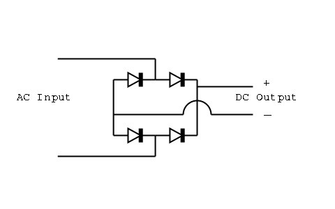
Single Phase Supply Circuit
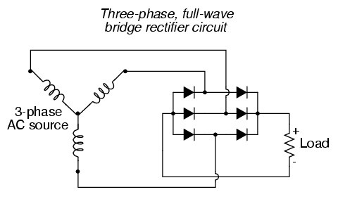
Three Phase Supply Circuit
-
Uncontrolled Bridge Rectifiers
In this type of rectifier, it utilizes diodes in the circuitry. As the property of diodes clearly states that the flow of current can be in a single direction. Hence this will be the basic component of uncontrolled rectifier so that the power in the rectifier remains same even the load requirement varies. Hence these are referred to as constant rectifiers.
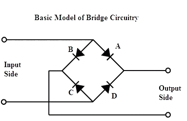
Basic Circuit Representing Uncontrolled Rectifier
-
3. Controlled Rectifiers (Bridge)
In this type of rectifiers instead of using normal diodes for this circuit silicon controlled rectifiers (SCR’s) are preferred. Instead of using only SCR’s, MOSFET’s and other controlling devices can be used. In this, the power value of output is varying based on the load requirements. This can be done by applying various voltages to it. The technique used here is for this purpose of changing the output voltage across the load is referred to as triggering.
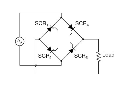
Bridge Rectifier Circuit Representing Controlled Rectifiers
The above are the types of bridge rectifiers that are classified based on the supply provided as well as further classified based on the output power has been controlled or varied. Based on the necessity the type of rectifier is chosen preferably.
Types of Bridge Wave Rectifiers

Diode
There are different types of bridge rectifiers that are classified based on different criteria. Consider different types of bridge rectifiers, which are classified based on the types of rectifiers such as uncontrolled rectifiers and controlled rectifiers. Diodes are called as uncontrolled rectifiers as diodes start conduction whenever the anode voltage is greater than the cathode voltage. But, in case of controlled rectifiers know as thyristors, even though the anode voltage is greater than cathode voltage, thyristors start conduction only when the gate terminal is triggered. Thus, we can trigger the gate terminal as per the requirement; hence, we can control the operation of the rectifier.
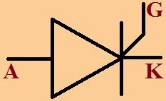
Thyristor
Bridge-wave rectifiers that are designed using thyristors are called as controlled bridge wave rectifiers. The operation of the rectification can be controlled by triggering the thyristors gate terminal whenever it is required. We know that the diode is a semiconductor device consisting of two layers (P-N) and thyristor is also a semiconductor device consisting of four layers (P-N-P-N). It can be used as open-circuit switch and also as a rectifier based on how the gate terminal of the thyristor is triggered.
Types of Bridge Rectifier Diodes

1N4007 Diode
There are series of didoes form 1N4001 to 1N4007 with different current and voltage ratings, but frequently 1N4007 is used for designing bridge-wave rectifiers. 1N4007 diode has absolute maximum ratings including voltage rating as 1000V peak repetitive reverse voltage VRPM, 1A average rectified output current IF(AV), 30A non-repetitive peak forward surge current IFSM, which can be operated at -55 degrees to +175 degrees temperature. Thermal characteristics as 3W power dissipation, junction to ambient thermal resistance 50 degrees/W. The didoes that are occasionally used to design rectifiers are series of didoes from 1N5400 to 1N5408 and 6A4.

1N5048 Diode
1N5408 bridge rectifier didoes are also used for some special applications and these are having ratings as maximum repetitive peak reverse voltage 1000V, maximum RMS voltage 700V, maximum DC blocking voltage of 1000V, maximum average forward rectified current 3A, operating junction and storage temperature range -50 to +150 degrees centigrade. ACPWM control for induction motor is a practical example in which a bridge wave rectifier designed using 1N5408 diodes.

6A4 Diode
These 6A4 bridge rectifier diodes have maximum ratings and electrical characteristics as maximum recurrent peak reverse voltage of 400V, maximum reverse voltage of 280V, maximum DC breaking voltage of 400V and maximum average forward rectified current of 6A. 6A4 diodes are used for bridge rectifiers in some special applications, an example is propeller display of message by virtual LEDs. Working of bridge rectifier circuit is similar irrespective of the diodes used to design rectifier, so let us consider the bridge wave rectifier circuit designed using diodes 1N4007, as it is used for bridge rectifiers in some special applicatins – for example a propeller display of message by virtual LEDs.
Bridge Rectifier Circuit
The bridge rectifier is a full-wave rectifying circuit that utilizes both the cycles for rectification. The only difference between this circuit and another circuit of the full wave with center-tapped transformer is that here the diodes are connected in bridge topology with no necessity of the center-tapped transformer in it.
As the center-tapped transformer usage made the circuit costly. This rectifier is designed to overcome this drawback as well as the efficiency remains the same in both the cases.
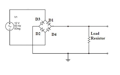
Bridge Full Wave Rectifier Circuit
The above is the bridge rectifier circuit that consists of the initial AC supply as well the four diodes connected in a bridge topology and a load resistor connected to it. At the initial stage, the power is supplied using a step- down transformer. Based on the characteristics are concerned for the requirements in a rectifier it can be the ratings of current or peak inverse voltage and so on the respective diodes have been chosen.
After the processing of input signals done at the diode bridge another stage for the rectifier will be its load. Here the load is taken as the resistor. Once rectification is done as the input AC is converted into pulsating DC but the requirement will be of pure DC. In that case, another component called a capacitor or inductor is added across the load. So that it can remove the ripples from the circuit and make the output smooth.
Bridge Rectifier Circuit Operation
Here the considered circuit is a single phase rectifier and there are four diodes in the bridge topology. These are further connected to the resistive load. The operation of the diodes is dependent on the cycles applied and based on the action of the diodes according to it.
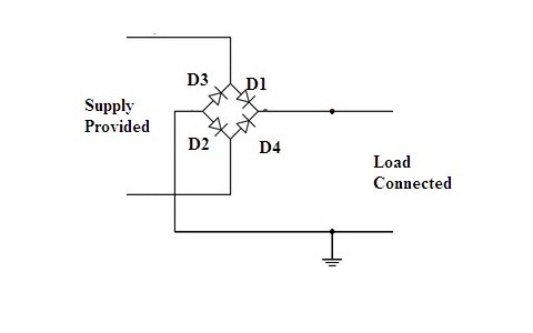
Bridge Wave Rectifier Operation Analysis
Let us consider the above basic circuit in order to analyze the bridge rectifier. The four are connected in such a diagonal manner that it looks like a diode bridge. Assume that the circuit is powered on indicating the first positive cycle will enter the circuit. As the positive cycle gets into the circuitry diode D1 and diode D2 will get into the forward bias condition and allows the path for the flow of current.
Whereas diode D3 and diode D4 will remain in reverse bias condition. Hence D3 and D4 will not conduct. As soon as the negative cycle gets into the circuitry D3 and D4 will be in conducting mode. D1 and D2 will remain in reverse bias condition. This results in the utilization of both positive and the negative halves of the cycle. One can observe whether it is a positive cycle or negative cycle applied results to the flow of current in the same single direction in order to satisfy the property of the diode. Hence the circuit becomes more efficient.
However after rectification there exist some ripples in the generated output that can be smoothened by the filtering technique. The ripple factor value is less in this type of rectifier compare to that of a half-wave rectifier.
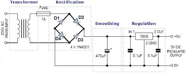
Working of the Bridge Rectifier Used to Convert 230V AC to 5V DC
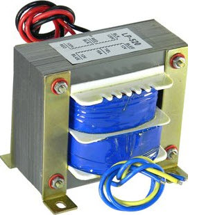
Stepdown Transformer
Step-down transformers are used to convert 230V AC (high voltage) into 12V AC (low voltage). This 12V output is an RMS value and its peak value is given by the product of square root of two with RMS value of the output of step-down transformer, which is approximately 17V. The working principle of transformers is based on Faraday’s laws of electromagnetic induction.
Uncontrolled Bridge Wave Rectifiers
Bridge Wave Rectifier
230V AC power is converted into RMS value of 12V AC or peak value of 17V (approx.), but 5V DC is the required power; for this purpose, 17V AC (peak value) power is converted into DC power, then it is stepped down to 5V DC. The 17V AC is converted into DC using a bridge-wave rectifier that consists of four diodes, which are called as uncontrolled rectifiers. Diode will conduct only in forward bias and will not conduct during the reverse bias. If anode voltage of diode is greater than cathode, then the diode is said to be in forward bias. Diodes D2 and D4 conducts during positive half cycle and diodes D1 and D3 conduct during negative half cycle.

Filter
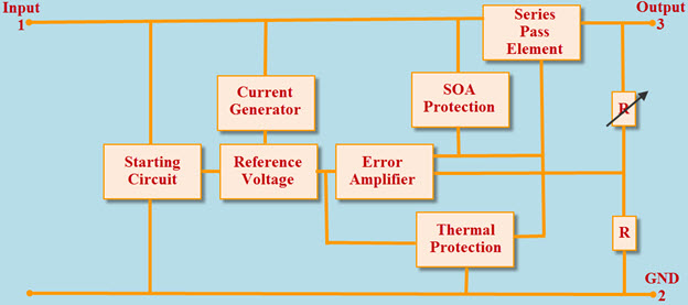
This charging and discharging of the capacitor make the pulsating DC into pure DC, as shown in figure. A step-down converter namely IC 7805 voltage regulator is used to convert 15V DC to 5V DC.
IC7805 Block Diagram
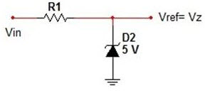
Block diagram of IC7805 voltage regulator is shown in the above figure. It consists of an operating amplifier that acts as error amplifier, zener diode used for providing voltage reference.
Zener Diode used for Providing Reference Voltage
In general, 7.2V to 35V is the operating voltage range of IC7805 regulator. If the input voltage is 7.2V, then it gives maximum efficiency and, as the voltage exceeds 7.2V efficiency will decrease as there will be loss of energy in the form of heat. So, heat sinks are used to protect the regulator from over heat. Even without using transformer, we can directly convert 230V AC into 5V DC using high-rating diodes. If we have 230V DC power supply, then we can directly convert the 230V DC into 5V DC using a DC-DC buck converter. Feel free to post your comments in the comment section below and encourage other readers to learn the basics about rectifiers.
Characteristics of the Full Wave (Bridge) Rectifier
The characteristics of the full wave rectifiers are similar for both center-tapped as well as a bridge rectifier.
(1) Ripple Factor
As discussed in the above circuit analysis of the bridge rectifier the output generated after rectification consists of some AC component present in it. These components are referred to as ripples. The ripples can be measured in terms of Ripple Factor.
It can be stated as the ratio between the presence of the AC component in the output generated to the obtained DC in the output. The symbol ‘r’ is used for representing the ripple factor.
[latexpage]
[
r=I_rms/I_DC
]
For the bridge rectifier, the ripple factor value is r =0.483. This ripple factor is important for the analysis of the efficiency of the circuit. Ripple factor value and the efficiency of the circuit are inversely related to each other.
(2) The efficiency of the Bridge Rectifier
The efficiency of the rectifier is defined as the ratio between the output of the DC power to the applied AC as the input power.
E= (generated DC power )/(applied input AC power)
The obtained efficiency of the bridge rectifier circuit is 81.2 %. As per efficiency wise compared to half wave circuit, it is more efficient and in comparison with a center-tapped transformer, it is very cheap. The overall analysis of bridge rectifier is simple to understand. However, it also requires filter support in order to make use of it in practical applications.
Advantages of a Bridge Rectifier
- In comparison to the half-wave rectifier, the bridge rectifier circuit is more efficient.
- There is no loss in the output power because of the utilization of both the halves of the cycle.
- There is no loss in the input signal as the output has fully rectified.
- Ripple factor value in the bridge rectifier is less because the circuit is more efficient.
- The mean in DC of its highest value is achieved because of full wave bridge rectifier circuitry.
- In terms of cost, it is very less because the concept of center-tapped transformer is eliminated from the bridge rectifier.
As per the analysis and the efficiency is concerned bridge rectifier has many advantages compared to that of disadvantages. But for practical applications, some necessary modifications must be done.
Please refer to this link to know more about Bridge Rectifier MCQ’s
Applications of Bridge Rectifier
- In the modulating radio signals to detect its amplitude concept of the bridge rectifier is essential.
- For electric wielding it requires a steady supply of DC in a polarized manner, this is possible by the full-wave rectifying circuit.
- Because of the efficient nature of the bridge rectifier, it is preferred as the part of the various appliances power supply unit.
- The high AC voltage can be converted into the low DC value with the capable nature of the bridge rectifier.
- For the powering up of the devices it may be LED or DC motor this type of rectifiers are preferably used.
Please refer to this link to know more about Carey Foster Bridge.
Please refer to this link to know more about Power Electronics MCQ’s.
The above are some of the applications of the bridge rectifier. Bridge rectifiers designing and analysis made it simpler to understand as well as its efficiency and ripple factor made it highly efficient. For practical applications consideration either center-tapped or bridge rectifier which one is preferred?
Image Credits
Bridge Rectifier Circuit Representing Controlled Rectifiers – Allaboutcircuits.com