The SCR turn ON method like SCR triggering or triggering of the thyristor is used to bring a silicon-controlled rectifier from forward blocking mode into conduction mode. In conduction mode, SCR can be characterized through less voltage drop, the impedance across anode, cathode & high anode current. The anode current value can be determined through the load and it permits the flow of current.
So, a silicon-controlled rectifier in forward conduction mode is known as its ON state & it can be called a close switch. SCR comes under the thyristor family, so both terms like SCR & thyristor are used as synonymous. This article discusses an overview of SCR triggering or triggering of thyristors.
What is SCR Triggering/Triggering of Thyristors?
An SCR (Silicon Controlled Rectifier) is a semiconductor device that comes under the family of Thyristor. This device includes 3-terminals, 3-junctions & 4-layers. The construction of SCR can be done with 4 alternate layers of semiconductor material. Here, the external p- region can be connected to the Anode terminal, the n-region is connected to the Cathode terminal & the p-region is connected to the Gate terminal.
Silicon Controlled Rectifier or SCR
A Silicon Controlled Rectifier is a switch that is either ON/OFF. The SCR includes two stable states like forward blocking (OFF – state) & forward conduction (ON – state). These two states are very significant as compared to other states. So, let us discusses these two states.
Switching the SCR from OFF – state to ON – the state is called the Turning ON method of SCR or SCR triggering. The SCR triggering mainly depends on different variables such as temperature, gate current, voltage supply, etc.
SCR Turn ON Methods
There are different techniques to trigger the SCR, Some of the SCR Turn ON techniques are discusses in detail.
- Light TriggeringGate Triggering
- Gate Triggering
- Forward Voltage Triggering
- Temperature Triggering
- dv/dt Triggering
Light Triggering
If a light signal is given to the SCR junction, then it produces ample energy to split the pairs of electron-hole within the semiconductor, so that the SCR will be activated.
Once the applied light’s intensity is enhanced above a nominal value, then the SCR will begin to conduct. It is not a simple method so it is not used regularly. This kind of triggering is mainly utilized in HVDC Transmission Lines.
Gate Triggering
Gate triggering most commonly used triggering technique for SCR. When a positive voltage is applied in between two terminals like gate (G) & cathode (K) then it can switch ON a thyristor in forward biased.
Once a positive voltage is provided at the gate terminal, then charge carriers will be injected within the P-layer thus reduces the width of the depletion layer.
When the applied voltage enhances, then automatically carrier injection will be increased, so the voltage will decrease at which forward break-over take place. For gate triggering, there are mainly three types of signals used to like DC gate, AC gate, and pulse gate.
DC Gate Triggering
In DC gate triggering, an ample DC voltage is provided in between the two terminals like gate & cathode and it can be possible by making the gate terminal positive as compared to the cathode. The current in the gate terminal can drive the thyristor into conduction mode. In this technique, a DC Voltage is given at the gate terminal to cause internal power dissipation. And another disadvantage is there is no segregation between the two circuits like power & control circuits.
AC Triggering
AC triggering is the most frequently used technique for triggering the SCR, particularly in the applications of AC. With appropriate isolation among the two control & power circuits through transformers, the silicon-controlled rectifier can be triggered with the phase-shift AC voltage which is derived from the major suppliers. The controlling of firing angle can be done by altering the gate signal’s phase angle.
But, simply one part of the cycle is obtainable for driving the gate to control the firing angle & for the remaining part of the cycle; a reverse voltage can be provided in between the two terminals like the gate & cathode. This is one of the AC triggering limitations & the other one is required for a separate step down otherwise pulse transformer for supplying the voltage to gate drive using the main supply.
AC triggering is classified into two types like resistance and RC triggering.
Resistance Triggering
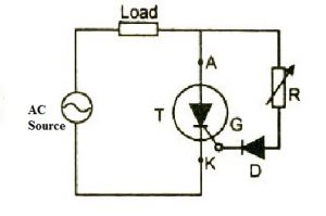
The circuit diagram of resistance triggering is shown below. In resistance triggering, the variable resistance is mainly for controlling the gate current. Based on its value, when the gate current’s magnitude achieves ample value, then the SCR will start to perform.

Resistance Triggering
Here, the diode ‘D’ is a blocking diode & it avoids the gate cathode junction from getting broken within the negative half cycle. So the gate circuit is simply resistive & the gate current is in phase through the voltage applied. This method helps achieve the highest firing angle.
RC Triggering
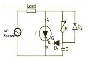
The resistance-capacitance triggering circuit is shown below. This technique is used to attain a firing angle above 90°. In the primary half cycle, the capacitor gets charged using the variable resistance ‘R’ up to the climax value of the voltage applied.

RC Triggering
This resistor controls the capacitor’s charging time. The starts triggering based on the voltage across the capacitor and when enough quantity of gate current supplies within the circuit. The capacitor in the second half cycle is charged up toward the negative crest value using the two diodes D1 &. D2. In this cycle, these diodes are used to avoid the gate cathode junction’s reverse breakdown.
Pulse Gate Triggering
Pulse triggering is the most frequently used technique for triggering the SCR. In this technique, a single pulse is applied to the gate otherwise number of pulses with high frequency. The main benefit of this technique is that gate drive is not continuous to turn ON the SCR & thus gate losses are decreased in larger amounts through providing single otherwise periodically appearing signals. Here, a pulse transformer is mainly used to separate the gate drive from the main supply.
Forward Voltage Triggering
In this technique, the silicon-controlled rectifier is connected in forward bias, so the anode terminal is more positive as compared to the cathode however this voltage can be drastically increased. Once the voltage enhances, then the depletion layer’s width of the ‘J2’ junction will be increased, so the minority carrier’s accelerating voltage at this junction will be increased.
At a specific voltage, Avalanche Breakdown will be there at the inside junction J2 thus the minority charge carriers will collide through atoms & release even more minority charge carriers. So this is called Forward Breakover Voltage, where the J2 junction at this voltage will turn into forward biased & the silicon controlled rectifier will turn into a conduction state. So, a huge current will supply throughout the SCR with an extremely less voltage drop.
Throughout the turn ON condition, the voltage drop in the forward bias of SCR ranges from 1 to 1.5 volts & this voltage may be enhanced through the load current.
Practically, this method is not used as it uses extremely high anode to cathode voltage. Once the voltage is above the VBO, then silicon controlled rectifier will be turned ON & a huge current will be supplied throughout it immediately, so SCR may be damaged. Thus, this kind of triggering is avoided in most cases.
Temperature Triggering
Temperature triggering is also called Thermal Triggering because the SCR will be turned ON by heating it. The reverse leakage current mainly depends on the heat. When the temperature is enhanced to a fixed value, then the hole-pairs can also be increased, so leakage current can be increased and further current gains of the SCR will be increased
This creates the regenerative action within the SCR as the value of (α1 + α2) reaches unity. At junction J2, the depletion layer width will be decreased by enhancing the temperature. So whenever the voltage in the forward bias is close to VBO, then we can trigger the SCR by enhancing the temperature of the ‘J2’ junction.
At a specific temperature, the junction’s reverse bias will break down & the device begins to conduct.
This kind of triggering happens in some situations mostly when the temperature of the device is high. In practice, this kind of triggering is not used as it causes the thermal runaway & thus the SCR may be smashed.
dv/dt Triggering
When the anode is positive more as compared to the cathode, then both the J1 & J3 junctions are connected in forward bias whereas the J2 junction is connected in reverse bias. As a result, the J2 performs like a capacitor because the space charges within the depletion area.
The capacitor’s charging current can be given as
IC = dQ/dt = d (Cjv)/dt
Based on differentiation product rule, we can get
= Cjd/dt + v dCj/dt
When the junction capacitance is stable, we can neglect the rate of change of junction Capacitance (dCj/dt). As a result, the last charging current is
IC = Cj dv/dt
Where the charging current is ‘IC’
The junction capacitance is ‘Cj’
The charge is ‘Q’
The applied voltage across the device is ‘V’
The junction capacitance’s rate of change is dCj/dt
The applied voltage’s rate of change is dv/dt
From the above-mentioned equation, if the amount of the applied voltage is high, then the current flow will enhance to activate the SCR without gate voltage. By increasing the rate of change of voltage, we can trigger SCR across the device instead of providing a huge forward bias voltage.
Please refer to this link to know more about Silicon Controlled Rectifier MCQs
Please refer to this link to know more about SCR Commutation MCQs.
But practically, this technique can be avoided due to a false trigger procedure & also this can generate extremely high voltage spikes across the silicon-controlled rectifier so there will be significant harm to it.
Thus, this is all about an overview of SCR triggering. The classification of SCR can be done based on the specifications as well as applications. The most popular SCRs are 2P4M, BT151, TYN608, etc. These are accessible in different types of packages that are used in various applications. The different packages of SCR are discrete plastic, plastic module, stud base, flat base & press pack. Here are a few questions for you, what is the digital triggering of SCR? What is Gate Turnoff Thyristor?