Knowing the heart rate data is very helpful while doing exercises, actively studying, etc. But measuring heart rate is a difficult problem. So, a pulse sensor is used to overcome this problem. This sensor is a plug & play heart-rate sensor, utilized by artists, students, athletes, mobile & game developers, makers who desire to know the existing heart-rate data to use in their live projects.
This sensor merges a simple optical heart rate sensor through a circuit. This circuit is used for noise cancellation & amplification to get consistent pulse readings very quickly. It uses 4mA of power at 5V, so it is very useful in mobile applications. This article discusses an overview of pulse sensors and their working with applications.
What is Pulse Sensor?
A plug-and-play sensor that is used to detect the heart rate data is known as a pulse sensor. This sensor is used by athletes, students, mobile & game developers, etc. This sensor clips on an earlobe or a fingertip by connecting right to an Arduino board through jumper cables. In real-time, the pulse rate can be monitored through an open-source monitoring app.

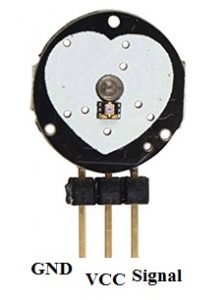
Pulse Sensor Pin Configuration
Here, a pulse signal is a variation within the blood level that happens when the heart forces the blood & a detector monitors the change in the blood volume. There are four methods to determine heart rate like a photoelectric pulse wave, electrocardiogram, phonocardiography & BP measurement but the pulse sensor uses the photoelectric technique.
Types of Pulse Sensor
Pulse sensors can be classified into two types based on the measurement technique of photoelectric pulse waves like transmission & reflection.
Transmission
Transmission type pulse sensor measures pulse signals by generating IR or red light from the surface of the human body. The signals can be generated by detecting the change in the flow of blood throughout heartbeats. This technique is restricted to some regions wherever light can simply go through like the earlobe or fingertip.
Reflection
The reflection-type pulse sensor which is used at present is ROHM. This kind of sensor is used to generate infrared, red color, or green color light toward the human body & measures the light which is reflected through a phototransistor or photodiode.
In the arteries of the human body, Oxygenated hemoglobin has the feature of absorbing light. So by detecting the rate of blood flow that changes heart tightening on time so that we can able to compute the pulse signal. The measurement of pulse wave signal using IR or red color light can be effected through IR rays limited in sunlight for avoiding stable operation. Due to this reason, semi indoors or indoors is suggested.
For measurement of the pulse wave outdoors, a green color light source includes a high rate of absorption within hemoglobin of blood. So ROHM type uses green color LEDs like a light source for transmission.
Pulse Sensor Kit
A pulse sensor kit includes the following.
- A color-coded cable with 24 inches including a male header connector. It can be easily connected to an Arduino board or a project without soldering
- An Ear Clip where the backside of this clip is hot-glued to the sensor backside so that one can easily wear it on the earlobe.
- Velcro Dots are perfectly sized at the clip side of the sensor and it is used to enfold around a finger.
- The velcro strap is used to enfold the sensor approximately to your finger.
- Transparent Stickers-3 are used on the front side of the sensor to defend it from sweaty earlobes & oily fingers.
- This sensor includes three holes at the external edge to sew it into anything.
Pin Configuration
The pulse sensor pin configuration includes three pins which are discussed below.
- Pin1 (Ground): This is a black color wire, used to connect to the GND terminal of the system
- Pin2 (Vcc): This is a red color wire, used to connect to +3.3V/+5V voltage supply
- Pin3 (Signal): This is a purple color wire, used to connect the output signal which is pulsating
Features & Specifications
The features of the pulse sensor include the following.
- This is a heart rate/biometric pulse rate detecting sensor
- This is a plug & play type sensor
- The operating voltage of this sensor is +5V/+3.3V
- Consumption of current is 4mA
- Length is 0.625”
- Width is 0.125
- Integral Amplification
- Circuit for cancellation of noise
The specifications of the pulse sensor include the following.
- The maximum current is 100mA
- Heartbeat deduction output LED
- VCC is +5v DC through high-quality regulation
- Light source – 660nm super Red LED
- Output data level is 5V TTL
Pulse Sensor Working Principle
The working principle of the pulse sensor is extremely simple. This sensor includes two faces where the first face is connected with an LED including an ambient light sensor whereas another face is connected with circuitry. This circuit aids in noise cancellation as well as amplification.
On the front side, the LED is connected to a vein of a human body (ear tips or Fingertip), however, it should be located directly on top of a vein. The LED produces light that will drop directly on the vein.
The veins in the body will have a flow of blood within them simply once the heart is pumping. So if we check the blood flow we can check the heartbeats also. If the blood flow is noticed then the sensor like ambient light will receive more light as they will be reflected through the blood, this small modification within received light can be analyzed on time to decide our heartbeats.
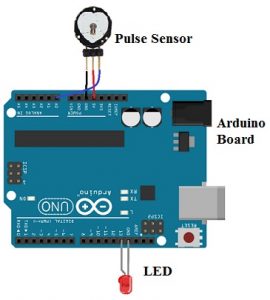
Pulse Sensor Circuit Diagram
The interfacing of the pulse sensor using an Arduino is shown below. Here, the sensor used in this is plug & play heart rate sensor. This kind of sensor is quite simple to understand as well as operate. Place the pulse sensor on the finger & it will detect the heartbeat by detecting the change within the light from the increase of blood vessels.

Pulse Sensor Interfacing with Arduino
The connection of the pulse sensor with an Arduino can be done like the following.
- The GND pin of the sensor is connected to the GND pin of an Arduino
- The sensor’s VCC pin is connected to 5V of Arduino
- The sensor’s ‘A0’ pin is connected to A0 of Arduino
- After that, LED needs to connect to pin-13 & GND pin of Arduino. So the LED will flash based on the heartbeat.
How to use Pulse Sensor?
While using the pulse sensor, it is very important how it is connected correctly. This kind of sensor can be covered through the vinyl tape, hot glue. Etc. It is also recommended to we should not use wet hands while handling these sensors.
The smooth side of this sensor must be connected on top of the vein & a small presser must be applied over it, this pressure can be obtained by using Velcro tapes or clips. This sensor can be activated by providing voltage supply to it as well as GND pins. This sensor uses 3.3V or 5V.
Once the circuit is powered, then the signal pin can be connected to the analog to digital converter pin of the controller to check the change within the o/p voltage. If we are using an Arduino board, then a preprogrammed code is used to make things very simple
Applications
The pulse sensor applications include the following.
- Sleep Tracking
- Monitoring of anxiety
- Alarm system
- Remote patient monitoring
- Health bands
- Advanced gaming consoles
Please refer to this link to know more about Color Sensor & Face Recognition.
Thus, this is all about an overview of the pulse sensor and its working. The stability & accuracy of this sensor drops far behind. An alternative to this kind of sensor is an easy pulse sensor because it is extremely stable. Apart from this sensor, a pulse oximeter sensor like MAX30100 is used to measure the heart rate with the blood oxygen. Here is a question for you, what are the alternate names of pulse sensors?