A combinational circuit like an encoder is used to perform the reverse process of the decoder. An encoder includes 2n inputs maximum and ‘n’ outputs. Therefore it encodes the data from 2n inputs into an n-bit code. It will generate a binary code that is equal to the input like active High. So, this circuit encodes 2n inputs through n-bits.
Encoding is nothing but the process of changing the numbers or symbols to a coded format. A priority encoder includes a priority function that allows it to produce an output equivalent to the high order input. This article discusses an overview of the priority encoder.
What is Priority Encoder?
A priority encoder is used to give binary-coded n-bits of output for signifying the location of the maximum order input of 2n inputs. If the minimum of two or above inputs is high simultaneously, the input including the maximum priority will take priority. This kind of encoder is used for controlling the requests of the interrupt by performing on the maximum priority demand.
This encoder has the priority function which depends on the input’s relative magnitudes. Therefore, the input including high magnitude must be encoded first. In several practical applications, these encoders select the inputs with maximum priority. So this kind of selection process is known as arbitration.
The best example of arbitration is, the computer has several input devices where these devices try to provide the data for the computer immediately. In those situations, this allows the input device that has the maximum priority between those devices which try to access the system simultaneously.
There are different forms of priority encoders available. Some of the best examples are discussed below like 8 to 3 type & 4 to 2 type
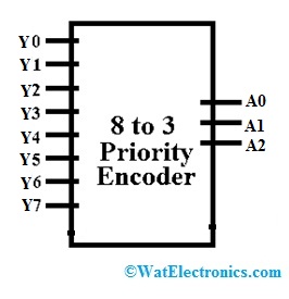
8 to 3 Priority Encoder
These are standard integrated circuits and the best example of this is the TTL 74LS148 which includes 8 active LOW inputs & provides 3 outputs.

8 to 3 Priority Encoder
First, this encoder generates the output like the highest order input. For instance, if the input lines are Y2, Y3 & Y5 then the output will be y5 because this is the highest order input. Once the highest order input like Y5 is removed then the subsequent maximum output would be for ‘Y3’ input & so on. The 8 to 3-bit priority encoder truth table is shown below. The inputs in the following truth table are Y0 to Y7 and Outputs are A0 to A3.
| Y7 | Y6 | Y5 | Y4 | Y3 | Y2 | Y1 | Y0 | A2 | A1 | A0 |
| 0 | 0 | 0 | 0 | 0 | 0 | 0 | 1 | 0 | 0 | 0 |
| 0 | 0 | 0 | 0 | 0 | 0 | 1 | x | 0 | 0 | 1 |
| 0 | 0 | 0 | 0 | 0 | 1 | x | x | 0 | 1 | 0 |
| 0 | 0 | 0 | 0 | 1 | x | x | x | 0 | 1 | 1 |
| 0 | 0 | 0 | 1 | x | x | x | x | 1 | 0 | 0 |
| 0 | 0 | 1 | x | x | x | x | x | 1 | 0 | 1 |
| 0 | 1 | x | x | x | x | x | x | 1 | 1 | 0 |
| 1 | x | x | x | x | x | x | x | 1 | 1 | 1 |
In the above tabular form, ‘X’ equals “don’t care”, that is logic “0” or logic “1”. From this truth table, the Boolean expression for the above type with data inputs Y0 to Y7 and outputs A0, A1, A2 is given as:
Output A0
A0 = Σ 1,3,5,7
A0 = Σ (Y7’Y6’Y5’Y4’Y3’Y2’Y1) + (Y7’Y6’Y5’Y4’Y3) + (Y7’Y6’Y5) + Y7
A0 = Σ (Y6’Y4’Y2’Y1) + (Y6’Y4’Y3) + (Y6’Y5) + Y7
A0 = Σ (Y6’ (Y4Y2’Y1) + (Y4’Y3 + Y5) + Y7)
Output A1
A1 = Σ 2,3,5,7
A1= Σ (Y7’Y6’Y5’Y4’Y3’Y2) + (Y7’Y6’Y5’Y4’Y3) + (Y7’Y6’Y5) + Y7’
A1= Σ (Y5’Y4’Y2) + (Y5’Y4’Y3) + Y6+ Y7
A1 = Σ (Y5’Y4’ (Y2+Y3) + Y6+ Y7
Output A2
A2 = Σ 4, 5, 6, 7
A2= Σ (Y7’Y6’Y5’Y4) + (Y7’Y6’Y5) + (Y7’Y6) + Y7
A2= Σ (Y4+Y5+Y6+ Y7)
From the above-mentioned outputs of the encoder, the final Boolean expression with the zero inputs can be defined as the following. The output expression for the priority encoder includes the following.
A0 = Σ (Y6’ (Y4Y2’Y1) + (Y4’Y3 + Y5) + Y7)
A1 = Σ (Y5’Y4’ (Y2+Y3) + Y6+ Y7
A2= Σ (Y4+Y5+Y6+ Y7)
These zero inputs can be neglected by allowing the execution of the last Boolean expression for the o 8 to 3 priority encoder outputs. From the above expressions, the simple 8 to 3 priority encoder circuit diagram can be designed through an individual OR gate.
Please refer to this link to know more about Encoder and Decoder MCQs
4 to 2 Priority Encoder
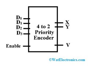
In 4 to 2 types, the total inputs are four namely D0, D1, D2 & D3, and outputs are two like X & Y. Here ‘Do’ has fewer priority inputs whereas ‘D2’ has high priority inputs. Once the above one input is ‘1’ simultaneously, the output will be the binary code that is equivalent to the high priority input. The truth table for the 4 to 2 lines is shown below.

4 to 2 Priority Encoder
This encoder treats the maximum input & generates output for that maximum priority input despite the other inputs values. So this encoder will treat the D3 as maximum input over D0, D1 & D2 where ‘D0’ is the lowest priority input.
If input ‘D2’ is high then the output will be 10 whether the D1 is high or low. The input condition like ‘V’ to confirm there is any input. So, when there is any input than “V” will be high. Input and output variables are D0 to D3 & X, Y, V correspondingly.
Truth Table
The truth table of 4 to 2 priority encoders is shown below.
| En | D0 | D1 | D2 | D3 | X | Y |
V |
| 0 | X | X | X | X | 0 | 0 | 0 |
| 1 | 0 | 0 | 0 | 0 | 0 | 0 | 0 |
| 1 | 1 | 0 | 0 | 0 | 0 | 0 | 1 |
| 1 | X | 1 | 0 | 0 | 0 | 1 | 1 |
| 1 | X | X | 1 | 0 | 1 | 0 | 1 |
| 1 | X | X | X | 1 | 1 | 1 | 1 |
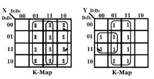
By using Karnaugh Map

Karnaugh Map
X= D2 +D3
Y = D1D2’ + D3
V = D0+D1+D2+D3
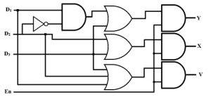
Like normal encoder expressions, this type of encoder expression is also the same however there is a statement like Y = 1 for input D1 simply when D2 input is low because according to the truth table, for D2 = 1, then ‘Y’ must be “0”. So, 4 to 2 priority encoder circuit diagrams using OR, NOT & AND logic gates.

4 to 2 Logic Diagram
Verilog Code
This type of encoder gives priority to every input. So, Verilog code for 8 to 3 priority encoder is shown below which includes design as well as test bench code. Outputs of this are set based on the input’s priorities. So if the encoder input is present with high priority, then inputs through fewer priorities are neglected & produce output based on the maximum priority input.
Design Code
module prio_enco_8x3(d_out, d_in);
output [2:0] d_out;
input [7:0] d_in ;
assign d_out = (d_in[7] ==1’b1 ) ? 3’b111:
(d_in[6] ==1’b1 ) ? 3’b110:
(d_in[5] ==1’b1 ) ? 3’b101:
(d_in[4] ==1’b1) ? 3’b100:
(d_in[3] ==1’b1) ? 3’b011:
(d_in[2] ==1’b1) ? 3’b010:
(d_in[1] ==1’b1) ? 3’b001:
(d_in[0] ==1’b1) ? 3’b000: 3’bxxx;
Endmodule
Test Bench Code
`timescale 1ns/1ps
module prio_enco_8x3_tst;
reg [7:0] d_in;
wire[2:0] d_out;
prio_enco_8x3 u1 (.d_out(d_out), .d_in(d_in) );
initial
begin
d_in=8’b11001100;
#10;
d_in=8’b01100110;
#10;
d_in=8’b00110011;
#10;
d_in=8’b00010010;
#10;
d_in=8’b00001001;
#10;
d_in=8’b00000100;
#10;
d_in=8’b00000011;
#10;
d_in=8’b00000001;
#10;
d_in=8’b00000000;
# 10;
$stop;
end // initial begin
endmodule
Difference between Encoder and Priority Encoder
- The main difference between encoder and priority encoder is, encoder changes one of 2n i/ps into an n-bit o/p. The encoder includes fewer output bits as compared to the input code.
- Similarly, this encoder is a combinational circuit and it is related to a binary encoder, apart from that the output it produces is based on the maximum prioritized input.
- This encoder is used to solve the issues of assigning a priority level to every input. Once input through a maximum priority is there, then all the remaining inputs through a lesser priority will be neglected.
- An encoder includes several input lines however only one of them is turned on at a specified time whereas a priority encoder includes above one input turned on at the same time.
Applications
The applications of the priority encoder include the following.
- A priority encoder is used in different applications as compared with the normal digital encoder. A larger priority encoder can be designed through cascading different priority encoders. Thus, this kind of encoder is used to decrease the number of required connections within a specific application where there are several inputs.
- In electrical and electronic circuits, priority encoder is used to reduce the requirement of connecting wires or application that includes several inputs. For example, suppose a microcomputer wants to read the standard QWERTY keyboard that includes 104 keys wherever simply one key would be pushed either LOW or HIGH at any one time.
- This also controls the interrupt requests by performing on the maximum priority demand to encode the flash analog output to the digital converter.
- Another common application is magnetic positional control which is utilized in the positioning of the robotic arm as well as navigations of the ship. In that situation, the encoder changes to a digital code from the angular location of a compass. So priority encoder defeats this drawback of the encoder and it provides a coded output through allocating a priority toward the input bits.
- Priority encoder converts several binary inputs into the binary depiction of the active input bit index through the maximum priority.
- These are frequently used once several components share a common resource otherwise within interrupt controllers. Using a PPC (parallel prefix computation), improves calculation as well as circuit timing.
Thus, this is all about an overview of the priority encoder. This is a special type of encoder, used to eliminate the problem associated with normal encoders. In this encoder, priority increases when the movement is in a downward direction. So the LSB (low significant bit) will have the lowest priority whereas the MSB (most significant bit) includes the maximum priority. Here is a question for you, what are the different types of encoders?