In electronic circuits, a relay is a switch that is operated electrically to control the circuit with low power or one signal. First, relays are used as amplifiers in long-distance circuits. The function of the relays is to re-transmit the replicated signal out from one circuit to another circuit. Relays are electromechanical type, solid-state type, and reed type. Similarly, distance relays are one of the types and versatile relays used for distance protection, which depends on the distance between the feeding point and the fault. The ratio of voltage to the current gives the impedance value in the time of distance protection operation. Impedance relays, admittance (Mho) relays, and reactance relays are the types of distance protection relays. This article gives a brief description of the Mho relay working principle and its operation.
What is Mho Relay?
Mho relay is referred to as voltage-controlled directional relay or admittance relay or high-speed relay. The operating torque can be determined by the V-I (voltage-ampere) element and the voltage element develops the controlling element. These types of relays are used to detect phase faults for long transmission lines, and at the point where there is an occurrence of synchronizing power surges. The mho relay is more sensitive and reliable because it is a combined unit of both distance measurement and direction.
Principle of Mho Relay
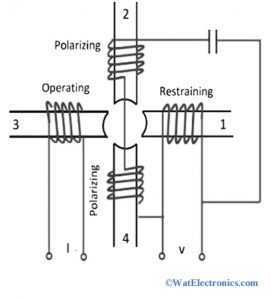
The working principle of the Mho relay depends on the impedance and the directional element. If the impedance measurement is less than the final point impedance, then it is considered as a fault that exists on the line between the relay and the final point. The mho relay diagram in the form of an induction cup structure is shown below. The interaction of fluxes due to poles 2, 3, and 4 produces operating torque. Due to 1, 2, and 4 poles controlling or restraining torque is obtained. A series capacitor is connected to provide memory action.

Mho Relay
From the figure, consider the controlling effect of the spring be -K3. Then the equation of the torque is given as,
Since operating torque is due to the V-I element and controlling torque is due to voltage element. So, the mho relay is also called a directional relay with voltage control.
T = K1V.I.cos(Ɵ-90°)-K3
Where Ɵ-90° represents positive when the current (I) lags behind voltage (V).
When the relay is at balance condition, the total torque becomes zero and therefore the equation is written as,
K1.V.I.cos(Ɵ-τ) – K2.V^2-K3 = 0
K1/K2 cos(Ɵ-τ) – K3/(K2VI) = V/I = Z
Z = K1/K2K2cos(Ɵ-τ)
If the controlling effect of the spring is neglected, then K3= 0
Operating Characteristics of Mho Relay
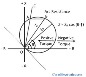
The operating characteristics of the Mho relay are shown below. From the figure, we can observe that, practically, the diameter of the circle is independent of voltage and current. But when a spring effect is taken into account at low voltage and current magnitudes, the diameter of the circle leads to a decrease.
Let the diameter of the circle is Zr = K1/K2, which is also referred to as the ohmic setting of the Mho relay.

Operating Characteristics of Mho relay
When the impedance is observed by the relay inside the circle, then it starts operating. As shown in the operating characteristics, the circle is passed through the origin, which shows that the relay is directional. Due to the natural directional property of the relay, only one pair of contacts is required to make quick tripping for clearing faults. This reduces the burden of VA on the current transformer.
The line OC represents the protected line with an impedance angle of 60° and 70°. The length AB represents arc resistance R, which is horizontal to OC.
When τ is equal to or less lagging than Ɵ, the circle is formed to fit around the area of the fault. Then the relay operates effectively and will be insensitive even at power swings. Hence the relay can be used to protect transmission lines with long and heavy loads.
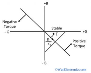
The operating characteristics of the Mho relay using the admittance diagram are straight lines, shown below. Consider τ is constant and the phasor admittance is Y that lies on a straight line. The Mho relays are applicable for EHV/UHV transmission lines with heavy loads because the property of threshold in Z-plane is a circle, which passes through the origin with diameter Zr.
Due to this, the threshold property is compact including the area of the fault. Hence at the power swings, the relay has less chance to operate. Since it is directional itself with voltage control and no need to use any directional element.

Admittance Diagram
The impedance determined by the relay is based on the type of fault. When the 3-phase fault occurs, then the relay will determine impedance with a positive sequence. If a line-ground fault occurs, then the impedance of the relay is the sum of negative, positive, and zero sequences. So, to actuate the relay, different formats(settings) of impedance are needed for different faults.
The relay should be manufactured with some sensitivity to obtain common impedance, which is positive impedance for app types of faults. A trip command will be issued by the relay if the positive impedance sequence is lower than the relay setting for all types of faults.
Applications
The applications of the Mho relay are listed below.
- It is used in the protection of UHV/EHV transmission lines
- It is used to protect long transmission lines because of its power swings.
- It is used to protect series compensated and uncompensated transmission lines to determine the location of the faults.
- It is used to determine impedance with a directional element based on the type of fault.
Thus, this is all about the Mho relay- definition, principle, operating characteristics, and applications. The purpose of the Mho relay, which is also called an admittance relay is to protect the long transmission lines with heavy loads. Here is a question for you, “What are the other types of relays used for distance protection?”.