In basic electronics, the circuits are divided into various categories based on the operation, structure, connection, etc. The electronics circuits are active, passive, analog, digital, and mixed-signal circuits. Consider a passive circuit with passive elements like resistor, capacitor, and inductor which are combined to form 4 types of circuits such as RL circuit, RC circuit, LC circuit, and RLC circuit. These passive elements in the passive circuit don’t generate power but store the energy. These passive circuits can able to act as passive filters. Usually, the absence of the resistor in the circuit doesn’t consume energy. But practically, even an LC circuit consumes energy due to the usage of non-zero resistance components and connecting wires. Depending on the connection of the reactive element capacitor or inductor in series or parallel with the load, the high pass filter or low pass filter is formed. Single-pole filters are formed by using these circuits. This article gives a brief description of the RL circuit in series and parallel.
RL Circuit Definition
An electrical circuit that consists of passive elements like a resistor (R) and an inductor (L) connected either in parallel or series with a driven current source or voltage source is known as an RL circuit. The presence of a resistor in the ideal form of this circuit will consume energy, and it is equal to the RC circuit and RLC circuit. It is also referred to as the first order RL filter or RL network.
A first-order RL circuit is the simple form of the circuit with a resistor and an inductor connected in series with a driven voltage source or current source. It is an analog electronic infinite impulse response circuit.
RL Circuit Derivation
From the below figure, consider the switch is closed at time t=0 and it remains closed permanently and produces step response of the input voltage. The current ‘I’ flowing through the circuit don’t reach to maximum value Imax and it is determined by the ohms law (ratio of V/R).
The limiting factor is due to the magnetic flux and the self-induced emf of the inductor. After some time, the flow of current becomes constant, induced current and magnetic field reduces to zero and the effect of self-induced emf gets neutralized by the applied voltage source. The RL circuit equation derivation is explained below.
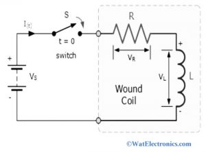
RL Circuit
Consider a basic circuit as shown in the figure above. From the above circuit, we observe that the resistor and the inductor are connected in series with an applied voltage source in volts.
Let the current ‘I’ be flowing in the circuit in Amps
IR is the current flowing through the resistor
IL is the current flowing through the inductor.
As we know that the resistor and the inductor are in series, the current flowing in the circuit is equal to the current flowing through both passive elements.
Let the voltage drop across the inductor and the resistor be the VL and VR.
By applying KVL (Kirchhoff’s Voltage Law) to the circuit we get,
V = VR + VL
That means the sum of the voltage drop across the resistor and the inductor must be equal to the applied voltage source.
The voltage drop VR across the resistor is given as
VR = I x R
Since I = V/R ohm’s law
The voltage drop VL across the inductor is calculated as
VL = L di/dt
The sum of individual voltage drops across the resistor and the inductor gives the total voltage in the circuit
Therefore, the RL circuit formula is written as,
V = I x R + L di/dt (where V = VR + VL)
The voltage drop across the inductor depends on the rate of change of current the voltage drop across the resistor depends on the current I. when the current I=0 at the time t=0, then the above formula gives the first order RL circuit differential equation.
The formula of current I at any instant of time t for the RL series circuit is given as,
I (t) = V/R (1 – e– Rt / L) in Amps
Where R = resistance in ohms
V = Voltage in volts
L = Inductance in Henry
t = Time in seconds
e = 2.71 (logarithm value)
Time Constant
It measures the time required to get some changes in the current and voltages of the RL and RC circuits. When the switch is closed, the time required for the current flowing through this circuit to reach its maximum steady-state value equal to 5-time constants is known as the time constant of the RL circuit.
When the value of the current reaches the maximum steady-state at a time constant of 5τ, the inductance in the inductor reduced to zero and behaves like a short circuit. Then the coil can be removed from the circuit effectively. The current flowing through the inductor (coil) is limited due to the resistance in the windings of the coil. When the elapsed time reaches 5-time constants, the voltage and current values reach the final value.
The time constant of the RL circuit calculates the time required to reach 63 percent of its maximum steady-state current value flowing through the circuit.
It is given as time constant τ = L / R
Phasor Diagram
To draw the Phasor diagram of the RL circuit, it is necessary to know the relationship between the current and voltage of the resistor and inductor.
Both voltage and current are in equal phase in the case of the resistor. Hence, the difference in phase angle is 0.
While for the inductor, the voltage and current are out of phase. That means the value of voltage leads the current by 90 degrees. The Phasor diagram is shown below.
The steps involved in drawing the Phasor diagram are given below.
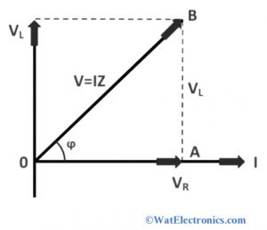
Phasor Diagram
Step1: The current I is taken as a reference and represented on the horizontal axis as shown in the figure. Since the resistor and inductor are connected in series, the current flowing through the circuit and the passive elements are the same (IR=IL=I)
Step2: For the resistor, the voltage drop VR is represented in the same direction/axis with current I. Because the current and voltage are in the same phase (VR=IR)
Step3: The voltage drop VL across the inductor is represented perpendicular to the current I. since the voltage leads 90 degrees to current and they are out of phase.
Step4: finally draw the resultant voltage V, which is equal to the sum of VR and VL
i.e., VR2+ VL2= V2 (taken from right angle triangle)
The phase angle is θ = tan-1 (VR2/ VL2)
Hence the phase angle difference between voltage and current for the series RL circuit is 0 to 90 degrees.
Power Factor of RL Circuit
In a series RL circuit, some amount of energy will be dissipated by the resistor and some amount of energy will be stored by the inductor.
The power delivered by the applied voltage source at an instantaneous rate is given as
P = V x I in Watts
The amount of power dissipated by the resistor at an instantaneous rate is given as
P = I2 X R in Watts
The potential magnetic energy stored/absorbed by the inductor is given as
P = VL X I = LI di/dt Watts
The power factor of this is the sum of dissipated power of resistor and magnetic energy stored by the inductor
P = I2R + LI di/dt Watts
Impedance
The opposition to the flow of an alternating current gives the impedance of the RL circuit. It is denoted by Z in ohms
V = IZ
Z= √ (R2 + XL2)
Where R= resistance in ohms
XL= inductive resistance
Transient Response of RL Circuit
The sudden application of current or voltage to the circuit containing a resistor, inductor, and switch leads to the response of a circuit, which is called the transient response of the RL circuit. It occurs only when the switch is turned off or on. Till the voltage and current values reach their maximum value, the switch will be closed.
The transient response of the RL circuit is represented graphically as shown below.
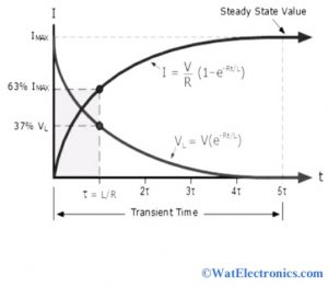
Transient Response
It is also known as step response of the RL circuit or impulse response of the RL circuit.
The impulse response of this circuit is represented in the decaying exponential function.
The step response of this can be determined by the charging behavior of the circuit. It shows how the signal in a digital circuit switches between low and high with time.
As we know, for resistor, VR=IXR, the current will have exponential growth.
When VL=V e(-Rt/L), the starting value of VL will be equal to the battery voltage at time t=0. When the switch is closed, then VL starts exponential decaying to zero as shown above.
The differential equation for growing current is given as,
di/(€-Ri)= dt/L
The differential equation for exponential current decaying is given as
di/ € – Ri = dt/L
RL Series Circuit
An electrical circuit that consists of a resistor (R) with a resistance (ohms) connected in series with an inductor with an inductance (Henry) and driven by a voltage source is called an RL series circuit. The current I flows through the circuit when an input AC voltage is applied.
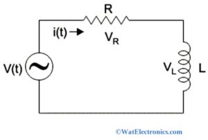
RL Series Circuit
Consider an RL series circuit with a constant voltage source and a switch, as shown in the figure below. This shows that the resistor is connected in series with an inductor across the supply voltage V in volts. The RL series circuit diagram is shown below,
RL Parallel Circuit
An electronic circuit that consists of an inductor and resistor connected in parallel with each other with an applied voltage source Vin is called an RL parallel circuit. The diagram of the RL parallel circuit is shown below. The output voltage Vout is taken across the inductor. Because of the parallel connection of a resistor and an inductor, the output voltage is equal to the input voltage. But the current flowing through the resistor and an inductor is different. It is not utilized as a filter and rarely used when compared to the series RL circuit.
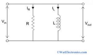
RL Parallel Circuit
RL Circuit Uses
The RL circuit uses are listed below,
- Used for RF amplifiers in DC power supplies, where the inductor is used to allow DC bias current and blocks the RF
- Used as high pass filter or low pass filter
- Used in chokes of tube lights
- Used in the filtering of low power signals and stores energy in the form of potential magnetic energy.
Know more about Kirchhoff Law.
Thus, this is all about an overview of the RL circuit – definition, equation derivation, time constant, transient response, step response, differential equation, impulse response, first order, series and parallel, power factor, impedance factor, Phasor diagram, and its uses. When the RL circuit reaches its steady state, the inductive resistance of the inductor starts decreasing and the value of resistance becomes zero at some point. Here is a question for you, “What is the RC circuit?”