In electrical power systems, a device is needed to measure the angle between any two AC systems like power networks or generators, which are synchronized with each other. To synchronize any two electrical systems, they must be operating at the same frequency at a phase angle of zero degrees. The synchroscope devices are used to measure the frequency and phase angle differences between two AC systems. If these differences are zero, then the two systems can be connected and synchronized with each other. When the two AC electrical power systems (unsynchronized) are connected, then the whole circuit gets damaged due to the heavy current flow. This article is all about an overview of the working of synchroscope and its types.
What is Synchroscope?
Definition: An instrument that measures and indicates the correct angle of two AC power systems, which are synchronized with each other, is called a synchroscope. The word synchronize indicates the same frequency, and zero phase angle of two AC electrical systems operating parallel with each other at an applied voltage.
This type of device indicates the phase difference between two AC generators which are connected in parallel to each other. And also checks or shows the running speed of the incoming generator and online generator.
Synchroscope Circuit Diagram
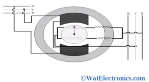
The synchroscope circuit diagram is shown below. It consists of a two-phase stator and rotor windings. The two stator windings are wound to one another at a right angle by using a phase splitting network. That means the current of one phase is leading at an angle of 90 degrees when compared to the current of another phase and generates a rotating magnetic field. While the stator winding is connected to the incoming generator/ alternator and a polarized coil is connected to the running generator/alternator.

Circuit Diagram
Working Principle
The synchroscope working principle is based on the principle of an AC motor. The synchroscope rotates when there is a difference in the frequency of the incoming generator and the running generator. It is designed in such a way that the incoming frequency should be greater than the running frequency. The pointer of the synchroscope rotates in a clockwise direction, only when the incoming frequency is greater than the running frequency. If the synchroscope indicates the phase difference of 0 degrees, then the two AC generators are in phase and synchronized with each other.
The synchroscope working is, the two-phase supply to the synchroscope is provided by the alternators. The third phase of the machine gets synchronized automatically if the other two phases are synchronized. The stator of the synchroscope gets the supply from the existing alternator. The phase shift between the supplies gives the difference between the frequency and the phase of the alternators, which are connected in parallel with each other. The speed of the incoming generator is indicated by the synchroscope. That means it checks whether the incoming generator is running fast or not.
It starts working only when the two alternators or generators, which have different ranges of frequencies, are connected parallel to each other. The rotor and the pointer becomes stationary only when the frequencies of the rotor and the stator are the same. If the frequency of the rotor and the stator are different, then the rotor starts rotating and the pointer of the synchroscope starts deflecting towards the clockwise or anticlockwise direction.
The change in applied frequency decides the speed of the rotating rotor. That means, the rotor starts rotating at high speeds when the differences of the applied frequency are large. Similarly, the speed of the rotor is less a difference in the supply frequency is less.
Synchroscope Construction
The synchroscope construction can be explained from the above figure. The incoming generator has two poles that are connected across two phases. The armature winding consists of two parallel windings that are connected to similar phases in the switch bus bar system. The resistance is connected in series to the half of the one winding. While the inductance is connected series with another half of the other winding as shown in the above figure.
The inductance helps to shift the flow of current at an angle of 90 degrees that relates to the flow of current in resistance. These two currents are supplied to the armature windings to produce rotating magnetic fields along with the field poles. The polarity of the two poles gets changed when there is a change in two phases of the incoming generator/alternator.
The rotating magnetic field along with the poles helps to rotate the rotor in a clockwise or anticlockwise direction and this results in the rotating of the pointer of the synchroscope. The two electrical machines should have similar voltages, frequency levels, and phase levels. The phase sequence gauge helps to measure the phase difference of the alternators/generators. The voltmeter is used to measure the voltage level of the alternator.
Function
The function of the synchroscope device is, it shows the frequency and phase difference of two synchronized electrical AC machines. They are an incoming generator/alternator (or simply incoming machine) and an on-line generator/alternator. The function of the synchroscope is to determine the running speed or frequency of the incoming generator or alternator.
If the pointer of the synchroscope rotated in an anti-clockwise direction, then the incoming generator will have a small amount of frequency. If the pointer of the synchroscope generator rotates in a clockwise direction, then the incoming generator will have more frequency.
Types of Synchroscope
There are two types of synchroscope. They are
Electrodynamometer Synchroscope
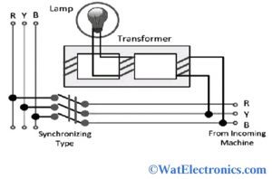
It consists of static and dynamic parts, which are the main parts of this type of synchroscope. The circuit diagram of the electrodynamometer synchroscope is shown below. One of the transformer windings is excited by the bus bar and the remaining two windings of the transformer are excited by the incoming machine. The transformer’s central limb has a lamp connection to determine the synchronization of frequencies.

Electrodynamometer Type Synchroscope
The lamp will not glow when the voltages of the incoming machines are out of phase with each other. In this case, the central limb of the transformer has zero resultant flux. The lamp starts flickering if the frequencies of the bus bar and the incoming machines are not the same. The frequency of the flickering or glowing lamp is equal to the frequency difference of the incoming machines and the bus bar.
The incoming machine and the bus bar are said to be synchronized if the lamp gives maximum brightness and less flickering. The speed of the incoming machines is indicated by an electrostatic device.
Moving Iron Synchroscope
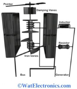
It consists of two fixed coils. One of the fixed coils has a small current value with series resistance. There are two cylinders mounted on the spindle and are energized by the pressure coil. The circuit diagram of a moving iron synchroscope is shown below.

Moving Iron Synchroscope
The two phases of the incoming machines have pressure coils, which are linked to each other. The resistance and inductance connected in series with the pressure coils create a 90 degrees phase difference between the two pressure coils.
If the frequencies of the incoming machines and the bus bar are the same, then the spindle Or pointer of the synchroscope starts rotating. The no. of revolutions of the spindle per second are used to determine the frequency differences of the incoming machines and the bus bar.
Thus, this is all about an overview of synchroscope– definition, circuit diagram, working principle, working, construction, function, and the types. Here is a question for you, “What are the advantages of synchroscope?”.