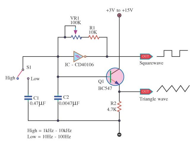
Square Wave Generator Circuit
Square wave can be defined as a non sinusoidal periodic waveform that can be represented as an infinite summation of sinusoidal waves. It has an amplitude alternate at a regular frequency between fixed minimum and maximum value with the same duration. Square wave generator are generally used in electronics and in signal processing. The square wave is the special case of rectangular wave. The square wave generator is just like a Schmit trigger circuit in which the reference voltage for the comparator depends on the output voltage. It is also said to be astable multivibrator.
Square Wave Generator Circuit Diagram Explanation with Waveforms
Square wave generator can be constructed using Schmitt trigger inverters like TTL. It is the easy way to make a basic astable waveform generator. While producing clock or timing signals, this astable multivibrator produces a square wave generator waveform that switches between HIGH and LOW .
As we know output of a Schmitt inverter is the opposite or inverse to that of its input. By giving hysteresis it can change state at different voltage levels. It uses a Schmitt trigger action that changes state between an upper and lower threshold level as the input voltage signal, increases and decreases about the input terminal. Here upper threshold level sets output and the lower threshold level resets the output.
This simple square wave generator circuit consists of a single TTL 74LS14 Schmitt inverter logic gate with a capacitor connected between its input terminal and ground and the positive feedback required for the circuit to oscillate being provided by the feedback resistor.
Assume that the charge across the capacitor plates is below the Schmitt’s lower threshold level. Therefore makes the input to the inverter at a logic ZERO level, resulting in a logic ONE output level.
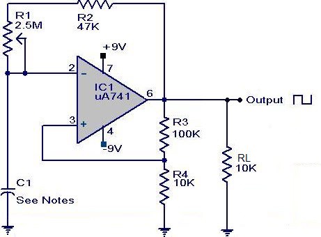
Square waveform generator circuit using op-amp
Working of Square Wave Generator
The resistor is now connected to the logic ONE level output while the other side of the resistor is connected to the capacitor, which is at a logic ZERO level. The capacitor is now starting to charge up in a positive direction through the resistor at a rate determined by the RC time constant of the combination.
While the charge across the capacitor reaches the upper threshold level of the Schmitt trigger and the output from the Schmitt inverter rapidly changes from a logic level ONE to a logic level ZERO state and the current flowing through the resistor changes direction.
The integral of a constant say ‘C’ will be ‘C’ multiple of t, where t is time across which the integration is taken place means that a positive constant will give a positive ramp and a negative constant will integrate to a negative ramp. By adding them together we get a triangle wave, then we got our square wave generator to produce a square wave from triangular wave.
Here change now causes the capacitor that was originally charged up through the resistor that begin to discharge itself back through the same resistor, until the charge across the capacitor plates reaches the lower threshold level. The inverter output switches states again with the cycle repeating itself over and over again as long as the supply voltage is present.
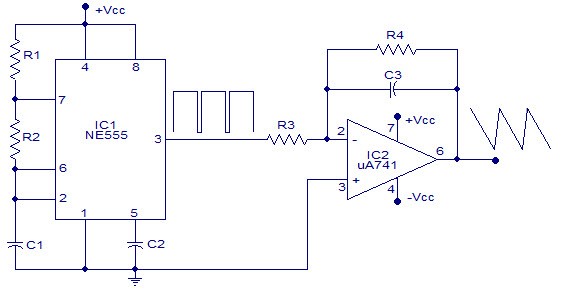
Square waveform generator circuit using 555 timer
The capacitor is constantly charged and discharging itself during each cycle between the inputs upper and lower threshold levels of the Schmitt inverter producing a logic level ONE or a logic level ZERO at the inverter output. The waveform is not symmetrical producing a duty cycle of about one third as the mark-to-space ratio between HIGH and LOW is 1to2 respectively due to the input gate characteristics of the TTL inverter.
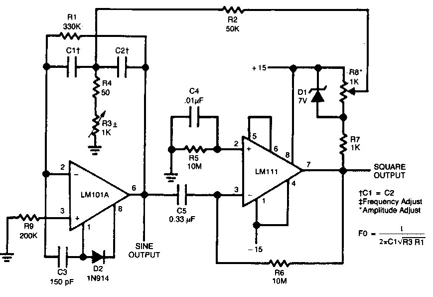
Square waveform generator circuit using LM IC
The feedback resistor must also be kept low to below 1k for the circuit to oscillate, around 300 k is good and by varying the value of the capacitor to vary the frequency. At high frequency levels the output waveform changes shape from a square shaped waveform to a trapezoidal shaped waveform as the input characteristics of the TTL gate are affected by the rapid charging and discharge. The frequency of oscillation for Square waveform generators is given as in the figure.
Waveforms and Frequency Range
With a resistor value between 100 to 1k and a capacitor value of between 1 to 1000uf. This would give a frequency range of between 1Hz to 1MHz high frequencies produce square wave generators distortion. Standard TTL logic gates do not work too well as square wave generators due to their average input and output characteristics and distortion of the output waveform and low value of feedback resistor required. This results in a large value capacitor for low frequency operation. The oscillators may not oscillate if the value of the feedback capacitor is too small. Astable Multivibrators can be made using better CMOS logic technology that operate from a min to max supply such as the Schmitt Inverter. This CMOS 40106 is a single input inverter with the same Schmitt-trigger action as the TTL 74LS14 but with very good noise immunity of high gain and excellent input/output characteristics to produce a more “squarer” output waveform as shown below.
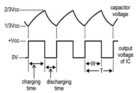
Square waveform
Circuit Diagram Of Function Generator
A function generator is usually a piece of electronic equipment used to generate different types of electrical waves over a wide range of frequencies. These can be either repetitive or single shot which requires an internal or external trigger source. It is used to generate waveforms may also be described as function generator ICs. Although square wave generators cover both audio and RF frequencies and are usually not suitable for applications that need low distortion or stable frequency signals. When those traits are required, another signal generator would be more appropriate. This function generator is one among the necessary gadgets of an electronic engineer. This is very useful in producing audio signals and even in inverter circuits.
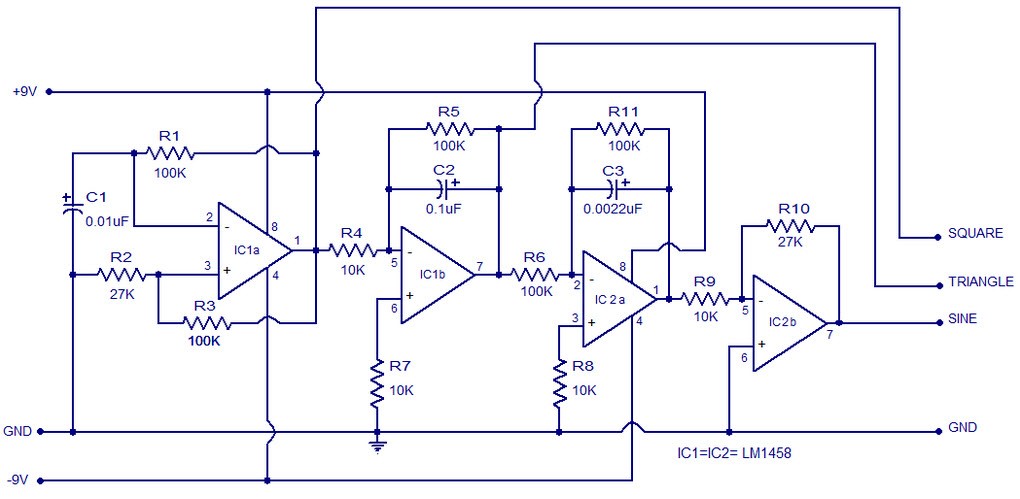
Function generator circuit
It is affordableFor engineers, We can choose various ways to generate various waveforms. It just needs a bunch of resistors and capacitors to build the entire circuit. We can able to produce square, sine and triangle wave with function generator.
After all these discussions we can able to say that the square wave is the inverse of the triangle wave. We can use function generator to produce different waveforms. Here is a question for you, what are the uses of the square wave generator?
Photo Credits:
- Square Wave Generator Circuit by eleccircuit
- Square waveform generator circuit using op-amp by next.gr
- Square waveform generator circuit using 555 timer by circuitstoday
- Square waveform generator circuit using LM IC by next.gr
- Function generator circuit by circuitstoday