In the year 1897, the discovery of the Braun tube took place and in 1899, Jonathan included it along with magnetic field and beam developing plates in order to sweep the trace. In the initial period of 1920, cathode ray tubes were used practically for laboratory calculations but experienced bad strength of the vacuum and cathode emitters. To eliminate this drawback, Zworykin in the year 1931 discovered an approach of sealing the cathode ray tube using a thermionic emitter. This approach permitted General Radio to construct an oscilloscope which can also be employed at external locations too. So, this is how oscilloscopes were invented. This article provides a clear description of the sampling oscilloscope, its working principle, sampling techniques, and applications.
What is a Sampling Oscilloscope?
This is the device that comes under the category of digital sampling oscilloscope that is employed for analyzing super quick signals. It can also be defined in the way that the sampling oscilloscope accepts multiple electrical signals and then collectively displays the signals as the output. The sampling oscilloscope principle is that it operates on the stroboscopic light where the single sample undergoes sampling at multiple sections of the wave through periodic cycles and then the collective picture is extended, amplified by corresponding minimal bandwidth amplifiers and those will be shown as the continual signal on the screen.
The main benefit of the device is that it can calculate even extreme high-speed events by using a device that has minimal bandwidth. Whereas the drawback is of the sampling oscilloscope is that it can only analyze either periodic or repetitive waves and the range of the frequency is based on the design of the oscilloscope.
With the sampling methods of the oscilloscope, it is easy to transform the provided signal into the minimal frequency domain. The minimal frequency signal holds a high-efficiency domain.
Operation
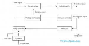
This section explains the sampling oscilloscope block diagram and explanation.
As the name of the device itself defines that, that it receives samples from the various continuous signals and then develops a comprehensive picture of the signal with the collected information. The obtained signal is now amplified using a low BPF and then the amplified signal is displayed on the screen. This signal is formed by uniting multiple dots related to each other in order to build the entire structure.
Every dot in the signal depicts the vertical deflection of the progressive phase in every consecutive cycle of the step signal. These are employed for examining a high range of frequency signals where the range can be up to 50 GHz or above. The frequency of the output signal is more than the sampling scope rate. It is nearly 10 sections per division or even high samples including the huge bandwidth of the amplifier which is nearly 15 G Hz. At the sampling phase, signals have a minimal frequency, and to gain high bandwidth it gets combined with the attenuator.
Even though it decreases the dynamic ability of the device, the sampling oscilloscope is restricted to repetitive signals and is not reactive for transient actions. Only the signals that have increased frequency and within the limit are only displayed.
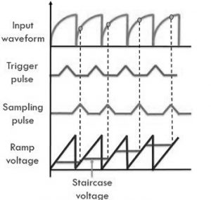
Before every sampling cycle, the trigger pulse simulates the oscillator and then it develops linear voltage. When the amplitude levels of both the voltages are similar, the staircase will be moved ahead by one step and it generates a sampling pulse where this allows a sampling gate for each sample of the received voltage wave. The resolution of the signal is based on the size of the steps that are in the staircase generator. The below picture shows the sampling oscilloscope working.

Block Diagram of Sampling Oscilloscope
Sampling Methods
There are various techniques of sampling but of many approaches only two were commonly implemented which are real-time sampling and equivalent sampling methods.
Real-Time Sample Method
In this sampling technique, a digitizer operates at an enhanced speed and this registers a greater number of points in a single sweep. The main functionality of this method is to collect a high range of frequency transient actions having high preciseness. The transient signal is so exclusive where the voltage or current level of the signal at any time period does not have a correlation with the closed signals.
These events will not get repeated, and because of this, it has to be registered in that frame itself as they happen. The frequency range of the samples is greater which is nearly 500 MHz and the sampling rate is approximately 100 samples per second. In order to accumulate a high range of frequency signals, high-speed memory is needed.
Please refer to this link to know more about Oscilloscope MCQs
Please refer to this link to know more about Sampling Oscilloscope MCQs
Equivalent Sample Method
This technique operates on the theory of assessment and prophecy where these are feasible only for repetitive signals. Here, the digitizer receives samples from multiple continuous signals. It might receive either one or more samples from every repetitive signal. In this way, the preciseness in accumulating signal will be enhanced. The frequency level of the output signal is more than that of the sampling rate scope. Again, here the sampling takes place in two forms which are random and sequential methods.
Random Method
This is the general type of sampling where this employs an internal clock where it gets corrected in the approach that it operates in correspondence to input signals and the wave simulated samples are considered continuously. The collected samples are consistent relating to time whereas random relating to trigger.
Sequential Method
Here, the samples are considered in correspondence to triggered and this is objective to time setting. When the trigger is spotted, there will be a recording of the sample but having a small delay. Here, one needs to ensure that the delay should be very minimal but should be properly defined. When the occurrence of the next trigger happens, it will be registered as having an increased time delay in view of the previous trigger. The delayed sweep lies in between the range of microseconds to seconds.
Advantages and Disadvantages
The advantages of sampling oscilloscope are:
- With this device, extreme speed electrical signals can be measured
- With the sampling methods, the input applied signal can be immediately converted into a signal which has a minimal frequency domain. In addition, the circuit generates an enhanced display.
- This holds the capability to react and accumulate data in the scenario of quick bits
The disadvantages of sampling oscilloscope are:
The sampling oscilloscope permits measurement to take place only for repetitive signals.
Applications of Sampling Oscilloscope
The sampling oscilloscope applications include the following.
- Employed in power conversion and signal conditioning
- Used in modulation measurements
- Signal analysis
- Conformance testing
- Automotive and protocol testing
Know more about Cathode Ray Oscilloscope.
This is all about sampling oscilloscope. Here, the article has provided a clear explanation of sampling oscilloscope working, block diagram, operation, sampling techniques, advantages, and applications. Know more about the delayed sweep of the sampling oscilloscope and how it shows impact?
