A distance relay is a fundamental device that trips the circuit breaker in the event of a fault. In low rating power systems circuits, the relay itself can trip the circuit, without the circuit breaker. The relay along with the circuit breaker together are used for the protection of transmission and distribution systems. Relays are classified in large based on the principle of operation. We have overcurrent relays, differential relay, frequency relay, etc. for which the operating quantity is current, the difference in current, and frequency.
Based on the operating quantity, the pick-up quantity is calculated. In the distance relay, the operating quantity is impedance. Based on the impedance of the transmission line, the relay operates. The impedance of the transmission line is calculated, based on the fault location, the voltage at the time of the fault, and fault current. Further, the relays are classified as mho relay, reactance relay, etc, based on the distance of protection or based on the span of the transmission line. These relays are used largely and have numerous advantages and most reliable for all fault cases.
What is the Distance Relay?
Distance relays are the protecting equipment that functions based on the distance of the fault point on the transmission line. The distance is calculated from the generating unit. Based on the distance, the impedance is calculated by evaluating the fault voltage and fault current.
Distance Relay Theory
The major necessity of distance relay has occurred due to the drawbacks of overcurrent or overvoltage relay. The main concept is depending on the type of fault, how to distance the protection can be provided with changes. For example, the reach of the line to ground (LG) fault is very much less than the reach of the three-phase (LLL) fault. So if we desire to provide protection up to a certain point we need to adjust the pickup point of overcurrent relays. This is not possible, since the relays are designed for one value of pick up current.
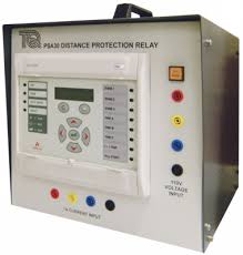
Distance Relay
Hence the biggest disadvantage of overcurrent relay is the fault current depends on the type of fault, therefore the length of line that is protected depends on the type of fault. Similarly, the distance of protection is also varied based on the source impedance. The lesser is the source impedance, the more is the distance covered for a particular type of fault. Hence the distance for which the overcurrent relay protects the line depends on source impedance also.
One more important factor that determines the fault current magnitude is generated voltage. The generated voltage again depends on the type of excitation. That is an overexcited alternator operates at a lagging power factor and similarly, an under excited alternator operates at a leading power factor. Hence these are all the factors on which the fault current depends. Based on these factors, the distance relay has been designed.
Fundamentally, it is designed for a particular distance of protection. Based on the fault location, the overall impedance beginning from the alternator is calculated. The impedance is calculated based on the ratio of voltage and current. The impedance of the transmission line hence becomes the operating quantity for the distance relay.
Relay Principle
The major principle of distance relay is it functions depending on the distance of fault in the transmission line. Its operation depends on the impedance between the point of fault and the point where the relay is installed. The impedance between the point of fault and the location of the relay is calculated based on the voltage and currents of the transmission line during the fault case. The impedance at that particular point becomes the operating quantity for the relay.
Distance Relay Diagram
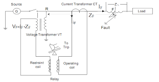
The following figure shows the structure of the distance relay operating principle. As shown, it starts with the source of electrical energy i.e, alternator. Then to measure the current, a current transformer is used in series with the line. Similarly, a potential transformer is used in parallel with the transmission line, to measure the stepped step down voltage.
Distance Relay Operation
These two parameters are fed to the relay for evaluating the impedance of the transmission line. The relay is connected to the circuit breaker, as shown. Whenever the relay operates, it sends the tripping signal to the circuit breaker, which immediately breaks or isolates the faulty line from the alternator. As shown in the diagram, Zf is the fault impedance. The fault is assumed to strike at the end of the transmission line.
Working of Relay
In order to evaluate the impedance, the voltage is calculated from the potential transformer and the current is calculated from the current transformer. Now for the operation of the relay, two important torque plays a vital role. One is deflecting torque and the other one is restoring torque. These two torques are most important for relay operation. In distance relay, the deflecting torque is produced by a secondary current of the current transformer and the restoring torque is obtained by the voltage of the potential transformer. In normal operating conditions, the restoring torque is greater than the deflecting torque.
Hence the relay remains in non-operating mode. But when a fault occurs the fault currents increases which increase the deflecting torque. Therefore, the deflecting torque becomes greater than the restoring torque, and the relay operates. Once the deflecting torque is increased, it closed the circuit by moving its dynamic parts. The trip circuit is closed.
Once the trip circuit is closed, the circuit breaker is energized. The tripping of the circuit can be basically an electromagnetic switch. When the circuit is energized, the closed contacts of the breaker are opened. On the opening of the contacts, the faulty line is separated from the healthy part of the system. This is how the fault line is isolated. On the opening of the contacts, an arc is formed in between the contacts, which need to be extinguished.
Distance Relay Characteristics
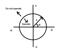
The characteristics of the distance relay can be explained using the RX diagram. The impedance of the transmission line is represented by the radius of the circle. As shown, the radius of the circle is Z. The phase angle between the R and X or also called an impedance angle to represent the position of the vector theta as shown. The characteristics consist of two axes. One is the R axis and the other one is X-axis. In the diagram, the vector position is shown for positive R and positive X.
Impedance Relay Characteristics
The operation can be explained in four quadrants. In the first quadrant, R is positive, X is positive, which means the fault impedance is greater than the normal impedance. Hence the relay will operate. In the second quadrant, the angle is negative, therefore the relay will not operate. Similarly in the third quadrant, the relay will operate.
In the region, where the relay will not operate, the restoring torque is greater than deflecting torque. And in the operating region, the deflecting torque is greater than the restoring torque. The distance relays are applied in short, medium, and long transmission lines.
Types of Relay
We have seen that distance relay is designed for a particular distance. Based upon the distance, and characteristics, distance relay can be classified as
Reactance Relay
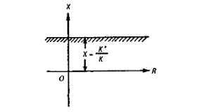
In this type, the X-axis is parallel to the R axis.
Reactance Characteristics
This type of relay will not operate for the resistance of the line. It will operate only for reactance
Advantages
- It will not respond to ARC
- It can be used for small transmission lines
- It can be able to sense the fault fast
Disadvantages
- In reactance characteristics, can not be used for fault locating relay
- It will not be able to distinguish between the fault in our station or other station
- It is not suitable for the long transmission line.
Impedance Relay
The characteristics are represented by a circle as shown before
Advantages
- The addition of the directional element can be used for better performance
Disadvantages
- It is a nondirectional relay that is the relay will respond to the fault on either side of the CT
- The characteristics curve is too large, so mal-operation is possible
- It can not be used for long transmission lines.
Mho relay or Admittance characteristics
Mho relays are most used for the long transmission lines.
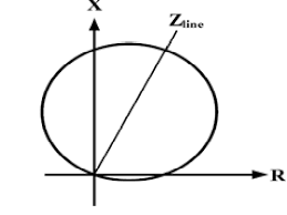
Admittance characteristics
Advantages
- The fault area is well-defined
- It is directional, so it can be designed to operate for a particular side
- It can be used for long transmission lines. It will respond to both resistive fault and reactive fault
Disadvantages
- It can not be used for small transmission lines.
Hence we have seen the working principle, operating characteristics, types, and advantages of distance relays. Most of the relays can be connected to microprocessors for fast and reliable operations. It may be thought that can we use distance relay for high-frequency operations?