A circuit that produces alternating and continuous waveforms is known as an oscillator. The waveform can be a sine wave, square wave, etc. based on their output frequency, oscillators are divided into various types. Electronic Oscillators’ frequency can be controlled by their input voltage, so they are termed voltage-controlled oscillators. There are many types of oscillators but mainly divided into two categories. One is Harmonic Oscillators or Linear Oscillators and the second one is Non-Linear oscillators. The nonsinusoidal waveforms are produced through the Non-linear oscillators whereas, the linear oscillators produce the sinusoidal waveforms. Under this linear Oscillators category, there are different types of oscillators like Colpitts oscillator, Feedback Oscillator, Phase shift oscillator, Armstrong oscillator, Negative resistance oscillator, Delay line oscillator, Robinson oscillator, Pierce oscillator, Clap oscillator, and Wien bridge oscillator, etc.
What is a Colpitts Oscillator?
An amplifier that converts DC signal as input to AC signal as output like a square wave or sine wave etc. and variable frequency drive by using positive feedback is known as an oscillator. Oscillators that use capacitor C and inductor L in the circuit are termed as an LC circuit which falls into the category of a linear oscillator. There are various methods to design this LC oscillator. The most familiar oscillators among those LC oscillators are Colpitts oscillator and Hartley oscillator. In these two types of oscillators, the Colpitts oscillator is the most used oscillator. Edwin Colpitts invented this Colpitts oscillator in 1918.

Colpitts Oscillator
Colpitts Oscillator Theory
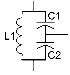
This oscillator forms a tank circuit by using two center-tapped capacitors in series with a parallel inductor and produces sinusoidal oscillations. The frequency of oscillations can be obtained by taking the values of the capacitors and inductors into consideration. In some ways, this oscillator is similar to the Hartley oscillator and in some ways, it varies.
The tank circuit connected between the collector and base of a transistor amplifier for obtaining sinusoidal output is the same in the Hartley oscillator and Colpitts oscillator. Due to this reason, the oscillator is called an electrical dual of the Hartley oscillator.
The difference between both oscillators is, In Hartley oscillator “a tapped autotransformer type inductor” is used whereas in Colpitts oscillator “a capacitive voltage divider” network is used i.e. tapped inductance is used by simple Hartley oscillator and tapped capacitance is used by Colpitts oscillator
This oscillator specifically designed for high-frequency sinusoidal oscillations with radio frequencies that will range from 10 KHz to 300MHz.
Colpitts Oscillator Circuit
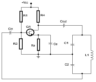
This is the circuit diagram of the Colpitts oscillator. Many oscillator circuits that produce sinusoidal waveforms use an LC resonance circuit except some electronic circuits such as RC oscillations, crystal oscillators, and few other oscillators don’t require additional inductances.

Colpitts Oscillator Circuit
Coming to the circuit, there is a bipolar junction transistor (BJT), field-effect transistor (FET), and operational amplifier similar to other LC oscillators. Two capacitors C1 and C2 form potential divider and thus this tapped capacitance acts as a feedback source. The Colpitts oscillator provides good frequency stability. In the circuit, there is a Re resistor which is good in providing stabilization to deal with temperature fluctuations.
Capacitor ‘Ce’ is connected in parallel to resistor Re. As a bypass capacitor, this capacitor gives a low reactive path to the amplified signal. The circuit is having an RC coupled amplifier and there are two resistors R1 and R2 which form a voltage divider for the circuit.
Colpitts Oscillator Working
The Colpitts oscillator uses a capacitive voltage divider network as a feedback source. C1 and C2 are placed across common inductor L forms tank circuits.
So, when the power supply is applied, the two capacitors C1 and C2 we are seeing in the circuit start charging and after it’s fully charged then discharging will take place through ‘L’ which causes damped harmonic oscillations.
Across C1 and C2, an AC voltage is produced by oscillatory current. While this discharging process takes place in the capacitor completely, the capacitors transfer electrostatic energy in the form of magnetic flux to the inductor which gives rise to inductor charge. Again when the inductor discharges, the capacitor charges. Due to this, inductor and capacitors charging and discharging process, oscillations will be generated.
Using the tank circuit resonant frequency, we can obtain the frequency of oscillations. This tank circuit is energy storage and it is also termed as an energy reservoir. This is due to the continuous charge and discharge of capacitors and inductor and for gaining constant feedback the two capacitances are ganged together.
Please refer to this link to know more Colpitts Oscillator MCQs
The resonant frequency of the LC tank circuit is given as
fr= 1/2π√ (L1*C)
Where ‘C’ is the equivalent capacitance
‘fr’ is a resonant frequency
C= (C1*C2)/ (C1+C2)
The transistor amplifier configuration is of a common emitter amplifier with 180 degrees out of phase with the input signal. An additional 180 degrees phase shift is required. For that two capacitors connected in series with an inductive coil which results in an overall phase shift of 360 degrees or 0.
Basing on the C1 and C2 values, the amount of feedback depends. By changing the values of the capacitors, the feedback voltage can be adjusted.
If the feedback is in a small amount, the circuit will not oscillate, and if the feedback is in high amounts, then the output sine wave will get distorted.
Basing on the capacitance ratio of C1 and C2, the amount of feedback gets developed.
Applications
The applications of Colpitts oscillator are
- In achieving greater stability and high frequency this Colpitts oscillator is very much needed.
- For producing continuous oscillations and undamped oscillations, these Colpitts oscillators are used
- The sinusoidal output signals with high frequencies will get generated by this Colpitts oscillator.
- Colpitts oscillators are effectively used in the development of radio and mobile communications
- The Colpitts oscillators can be used in sensor applications like a temperature sensor. Due to the highly sensitive device used in this sensor, it directly senses from the surface
- It is also used in a wide range of frequency involved applications
Know more about Wien Bridge Oscillator MCQs.
Please refer to this link to know more Oscillators MCQs
In this, we came to know the detailed view of oscillators, the different types of oscillators, and the complete description of the Colpitts oscillator, its circuit diagram, it’s working, and its applications. Here is a question for you, what is an oscillator circuit?