An operational amplifier is a voltage amplifier that has a differential input and a single-ended output. It is used with various external feedback components like capacitors and resistors. An operational amplifier is one such circuit that is capable of performing various calculus operations like integration and differentiation. It can be configured accordingly to perform such calculations. In the op amp integrator circuit, the output produced is nothing but the integration of the input voltage with respect to the total time.
A passive integrator is one such circuit that does not contain any active components like transistors and op-amp. On the other hand, an active integrator consists of active components which produce high output voltage and low resistance. We can use operational amplifiers as part of negative or positive feedback circuits. An integrating circuit is basically an inverting amplifier that consists of capacitors that are placed at appropriate locations.
What is an Op Amp Integrator Circuit?
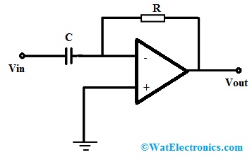
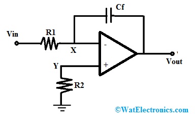
The basic op amp integrator circuit has an op-amp with a capacitor. The capacitor is placed between the inverting input and the output. There is a resistor ‘R1’ from the inverting input to the circuit input. When we apply a signal to the inverting input, the output produced is the reverse of the output produced in a CR integrator network.

Op Amp Integrator Circuit
The output voltage ‘Vout’ generated by the op-amp for a particular input (Vin) can be given by the following op amp integrator equation.

Where
‘Vout’ = output voltage of the integrator in volts
“Vin’ = input voltage of the integrator in volts
‘T’ = time interval after the input voltage is applied across the input terminals in seconds
‘R’ = Value of resistance in the resistor of the integrator circuit in Ω
‘C’ = Value of capacitance in the capacitor of the integrator circuit in Farads
‘c’ = Integration constant. Here, it is the output starting voltage.
Ideal Op Amp Integrator
In an ideal op-amp integrator, a capacitor ‘C1’ is connected between the inverting input terminal and the output. When the input voltage is zero, no current will flow through the input resistor ‘R1’, and no charge will flow through the capacitor. The output voltage will also remain zero.

Ideal Op Amp Integrator
When a constant positive voltage is applied across the input terminal of the integrating amplifier, the output voltage will start decreasing at a linear rate. On the other hand, when a constant negative voltage is applied across the input terminal, the output voltage will start increasing at a linear rate. The change in the output voltage is proportional to the input voltage.
Op Amp Integrator Ramp Generator
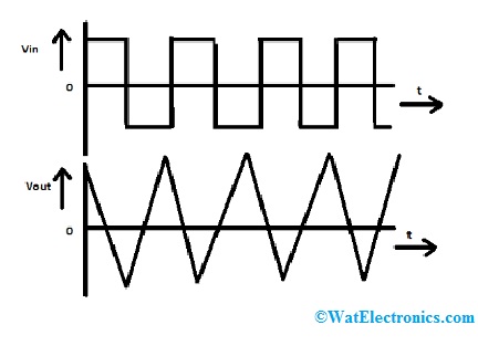
When we give a continuous-time square wave as input to the integrating amplifier instead of using step input, then we see a change in the input signal amplitude. This change causes the feedback capacitor to charge and discharge continuously.
The output of the integrating amplifier is a triangular wave that has a frequency whose value is dependent on R1Cf. This value is also known as the time constant for the circuit. This type of circuit is also known as the ramp generator.
During the positive half-circle of the input, there will be a constant flow of current through R1. As there is no current flow in the op amp integrator circuit, the entire current will flow through ‘Cf’. This will ensure that the capacitor is charged. As the capacitor is connected to the ground, the output voltage is the same as the voltage across the capacitor.
During the negative half-circle, the direction of the flow of current is reversed. This will cause the capacitor to get linearly charged thereby producing a positive ramp output.
AC or Continuous Op-Amp Integrator
When the square wave input signal is changed to a sine wave having a varying frequency, then the OP-amp integrator will stop behaving like an integrator and will start to behave like a low pass filter. It will begin to pass the low-frequency signals and attenuate the higher frequencies.
When the frequency is zero, the behavior of the capacitor is similar to that of an open circuit. The output will give no feedback to the inverting input. The circuit will start showing the behavior of an inverting amplifier that has a very high gain.

Input and Output Signals
This will cause a saturation of the generated voltage. As there is a gradual increase in the frequency, the capacitor will start to get charged. When the frequency is considerably higher, the capacitor will behave like a short circuit.
AC Op-Amp Integrator with DC Gain Control
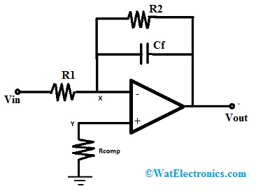
In an op-amp integrator with DC control, a resistor having a very high value of resistance is connected in parallel to Cf which is the feedback capacitor. The closed-loop gain of the op-amp will be similar to that of a normal inverting amplifier that is R2/R1.
The circuit will behave like a normal integrator at input signals having lower frequencies. However, at higher frequencies, the capacitor will behave like a short circuit and will bypass R2. The reactance will cause the gain of the amplifier to reduce.

DC Gain Control Circuit
A gain of R2/R1 is attained. With the increase in input signal frequency, the feedback capacitor will start to get charged. It will start to behave like a short-circuit. As a result, the gain will start to decrease linearly.
Advantages
The advantages of op amp integrator include the following.
- Op-amp circuits can be made to perform both integration and differentiation.
- The circuit can be modified to give various applications.
- Op-amp integrators produce an output voltage that is almost 100 times greater than the input voltage.
Please refer to this link to know more about Operational Amplifier MCQs
Applications
The applications of op amp integrator include the following.
- Op-amp integrators can perform calculus operations like integration and differentiation.
- Op-amp integrators are used in analog-to-digital circuits.
- Integrators are also used in the industrial instrumentation trade. This application is called a totalizer.
- Op-amp integrators are also used in wave shaping applications and ramp generators.
Please refer to this link to know more about How to select an op-amp?
So, this is all about an overview of an op-amp integrator and its working. As we can see these are very useful circuits from the industrial point of view. They are used for numerous applications and the output voltage produced has a phase sight of 180 degrees with respect to the input voltage. Here is a question for you, what is an integrator?