MOSFET Switch is a metal oxide semiconductor device that consists of three terminals known as source, gate, and the drain. It comes under the classification of basic field-effect transistor (FET). The conduction is either dependent on the flow of electrons or holes as per the type of the channel.
This makes the device to be unipolar. Other than three terminals there exists one more type of terminal that is referred to as the substrate or the body but it is neither used in input nor output connections. These types of transistors are preferred in many of the most frequently used analog and digital circuits. The functionality of the MOSFET is dependent on the width of the channel that is varying.
In Which Region MOSFET Operate as Switch?
MOSFET has many regions for operation based on its ability to perform conduction for the applied biasing voltage and the flow of charges.
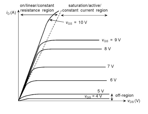
(1) Ohmic Region
In this region for a fixed value of the drain and the source voltage the channel width will change according to the gate and source voltage. Under this condition FET will work as a variable resistor that is controlled by the voltage. There is no value of Pinch-OFF present in this case as the source to drain voltage is constant. This is the reason the current at the drain terminal tends to increase.
(2) Saturation Region
In this region, the current at the drain terminal is dependent on the voltage at the junction of the gate and the source terminals other than the voltage at the drain and the source terminals. When the value of the voltage that is at the gate and the source terminals is zero the maximum amount of drain current flows through the device. When the polarity of this voltage is shifted to negative the current at the drain tends to decrease.
At some point, if the applied voltage is maintained to be constant in that case the value of the current flows is also maintained to be constant.
(3) Cut-Off Region
In this region drain current goes to zero value even when a gate to source voltage is applied. Then at this stage, the device is considered to be OFF.
Hence the above discussed are the three regions of operations of the FET. In order to make the MOSFET to operate as a switch saturation region is preferred.
MOSFET as a Switch Circuit
MOSFET as discussed earlier saturation region is preferred to make it work as a switch. Once the voltage at the gate and the source terminals are crossed the levels of the threshold value of the voltage a channel is created for conduction or the existing channel tends to conduct. Hence the channel formation after the application of the voltage or the existing channel conductance then this functionality of the MOSFET is classified as Enhancement mode or depletion mode MOSFET.
When the voltage value of the gate and the source is greater than the threshold then it is referred to as the region of saturation where the device tends to turn ON. But it is dependent on the voltage across the terminals of the drain as well as the source. The resistance is maintained to be constant during this stage.
When the value of the voltage at the terminals of the gate and the source is less than the threshold the device turns to be OFF this region of operation is known as the cut-off region. As the device turning ON and OFF is dependent on the value of the voltages applied this device is known to be voltage-driven.
In this way, a MOSFET is considered to be as a switch. Based on the types of the channels used in the MOSFET it is classified as p-channel and the n-channel MOSFET.

I-V Characteristic of N-Channel MOSFET
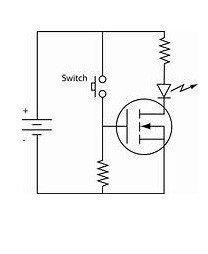
N-Channel MOSFET Switch Circuit
In this switching circuit where n-channel is used and the gate-source terminals are supplied by the positive polarity of the voltage. This positive polarity makes the device that is connected to the transistor makes it turn ON. The arrow marks in the symbol indicates the direction of flow of charge carriers.

The symbol for N-Channel MOSFET Working as a Switch
P-Channel MOSFET Switch Circuit
As the channel considered here is made up of p-type then, in this case, the negative voltage must be applied to the gate so that the device gets turned ON. In order to use MOSFET for switching instead of the resistor, the preference must be given to the inductor and the capacitor as the loads. The reason is that it can act as protection ailments for the devices that are operated with these transistors.
The regions that are preferred during the switching application is that it should be completely OFF that is possible during the cut-off stage and the other is completely ON that can be achieved by making the device to operate in the saturation region.
In this way, the transistors are possibly designed so that based on the areas of its applications these varieties of transistors can be implanted and utilized. Now can you choose which model is preferred to make this MOSFET to work as a switch.
Please refer to this link to know more about MOSFET MCQs
MOSFET Switching Frequency
The switching frequency can be determined by the time taken for switching, it can be either for turning ON or for turning OFF. This can be provided while manufacturing in the respective datasheet of that device.
The time taken for the device to reach the level of the defined threshold is known as the delay time. The rise time is referred to as the final value reached by the device after crossing the limit of the threshold. Here it is the combination of the delay as well as the time required to rise.
Please refer to this for How to Select a Transistor.
Please refer to the link IRFZ44N MOSFET Datasheet.
Know more about Enhancement MOSFET.
Know more about MOSFET Circuits for Electronics Projects.
The time taken by the device where its voltage value at the gate and the source tend to drop below 90% for the voltage-driven by the gate is known as delay time to turn OFF. The time taken for which the voltage reaches a particular threshold beyound which the device turns off is Fall time. This turn OFF time is the combination of the delay as well as the fall time. Can you tell which type of FET is better when switching is considered?