A comparator circuit with a large gain of open-loop requires a small amount of noise to trigger the circuit. If such comparators are used as zero-crossing detectors and get affected by false triggering leads to unnecessary problems. This may lead to the false indication of zero crossings of the noise signal rather than the actual signal. This unnecessary switching of levels can be avoided by using a circuit known as Schmitt trigger. This circuit was invented by the scientist in America otto H. Schmitt in the year 1934. Hysteresis is provided in these circuits such that each rising and falling edge has a different level of the threshold voltage. This Schmitt trigger circuit is also referred to as ‘Regenerative Comparator’.
What is a Schmitt Trigger?
An electronic circuit whose feedback is positive and able to hold the level of output until the applied signal is above the threshold. This type of circuit is defined as a Schmitt trigger. The basic purpose of such circuits is to convert analog signals into digital ones. The transitions at the output can be from high to low or low to high at the various threshold levels because of the hysteresis exhibited by the circuit.

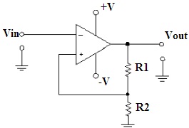
Schmitt Trigger using Op Amp
Schmitt trigger works as a basic multivibrator that possesses two stable states. The output change from one state to another requires triggering by the input applied. Further, these are classified into two types. They are:
Non-Inverting Schmitt Trigger
If the output obtained is attached to the negative terminal of the op-amp is known as non-inverting Schmitt trigger.
Inverting Schmitt Trigger
If the element obtained as output is attached to the positive terminal of the op-amp is referred to as inverting Schmitt trigger.
What are UTP and LTP in Schmitt Trigger?
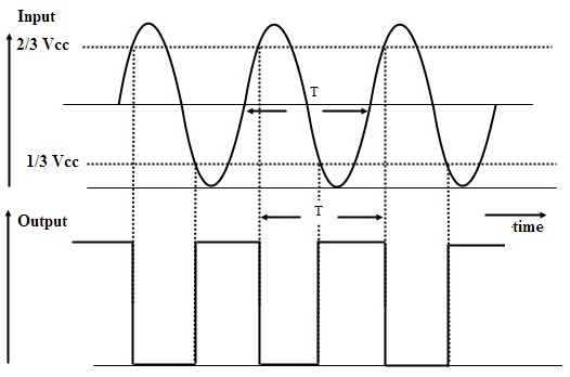
If the sinusoidal voltage is applied as the input to the circuit. Let us assume initially the output is at its positive state of saturation. When the voltage at the input tends to fall it affects the voltage at terminals. The voltage at the inverting terminal will be greater than the non-inverting one. This type of transition of output due to the application of input from positive to negative is defined as the upper threshold. The point at which the input signal is greater than the chosen value off threshold is referred to as Upper Trigger Point (UTP).

Schmitt Trigger Output
Similarly, if the value of the input is such that the output, makes the transition from negative to the positive situation is determined as the lower threshold. The point at which the output is considered as high and the applied input is below the threshold is known as Lower Trigger Point (LTP). This process of choosing UTP and LTP is known as Hysteresis. The process of triggering continues in the circuit until the input sine is present, as well as the DC supply to the op-amp circuit, is in ON state.
Schmitt Trigger using IC 555
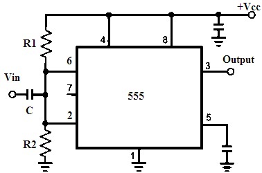
The circuit for IC555 timer used as Schmitt trigger is

Schmitt Trigger using IC555
- The 4 and 8 pins are the supply (Vcc) pins of this timer.
- 2 and 6 pins are connected together with a capacitor in common and the input is provided through this capacitor.
- This common point is facilitated with the voltage divider circuit by using resistors R1 &R2.
- If the applied input is greater than the value of the upper threshold the output will be high.
- If the applied input is lower than the lower value od threshold then the output of the circuit is low.
- The value of the output is retained if the applied is in between these upper and lower thresholds.
- 2/3 and 1/3 Vcc are the thresholds in this circuit.
- Based on the comparison with these thresholds either the flip-flop will be Set or Reset and the change in output states is noticed.
- Once the input with an amplitude greater than Vcc/6 is applied the flip-flops accordingly get sets or resets based on the type of cycle either positive or negative.
Schmitt Trigger using Transistors
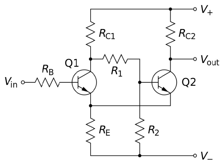
A Schmitt trigger designed with a transistor consists of five resistors and two transistors. When the supply is provided to the circuit the resistors R1, R2, and RE(Emitter Resistance) form a potential divider circuit across supply and the ground.

Schmitt Trigger using Transistors
Working
Due to the divider circuit, the supply is provided to transistor Q2 by moving it in forwarding biasing mode and begins to conduct. Voltage drop is seen across Re because of the flow of current through it.
This voltage drop makes the Q1 transistor be in reverse bias and makes it operate in the cut-off region. The voltage at the collector of Q1 tends to rise toward the level of Vcc. This voltage gets coupled to the transistor Q2’s input and it remains in conducting region due to the resistor R1.
The input Ac signal when applied to the Q1 if it is above the threshold then it begins to conduct. This point of a threshold is referred to as the Upper Trigger Level (UTL).
Once the Q1 begins to conduct the drop of voltage across the collector of Q1 is at the minimum and the negative signal flowing through the base of Q2 reduces the flow of current across the emitter and results in the decrease of the voltage drop across Re.
This makes the transistor Q1 to conduct and makes Q2 be n cut-off. The process is continued until Q1 reaches saturation mode.
When the negative half of the cycle is about to pass Q2 is in cutoff until the level of input falls below the lower value of trigger. Once it is passed (LTL) Q1 is reverse biased and tends to increase the flow of voltage at the collector of Q1. This drives the base of the Q2 by the resistor R1.
Hence Q2 beings to conduct resulting in the drop in voltage across the resistor Re increases an makes the transistor Q1 to drive it to cut-off region. this level is continued until the positive cycle of the signal is noticed.
Schmitt Trigger Applications
The applications of Schmitt Trigger are
- To convert sine into square waves these circuits are used.
- It can be used as simple switches and use it as ON or OFF controllers.
- In the signal conditioning to eliminate the noise from the signals and use it in digital circuits, these triggering circuits are used.
- The negative feedback in closed-loop configurations of these circuits can be used as Relaxation Oscillators, Function Generators, and also used in power supplies switching.
- These Schmitt triggers are used as level detectors.
FAQs
1). What does a Schmitt trigger do?
Schmitt trigger is a circuit that provides two levels of the threshold for the rising and the falling edges of the applied AC signal. Based on which the output signals are generated.
2). What are the triggers of electronics?
In Electronics triggers are the circuits or the pulses which initiates the action of the other components.
3). Why is the Schmitt trigger used?
Schmitt triggers avoid the errors present in the input signal applied. It eliminates the noise from it and generates the output square wave.
4). What is a trigger with an example?
A circuit in which the change in output is due to the change in the applied input at a certain predetermined point of operating is known as a trigger.
Example: Temperature control devices, Schmitt Triggers, etc…
5). What is a trigger switch?
A switch that is actuated based on pulling of a trigger is known as a trigger switch.
Schmitt triggers are used are inverters and buffers in the digital world of logics. These triggers can be converted into latches and vice-versa. Even the switches which are operated based on temperature have also utilized these circuits. After discussing the basics of Schmitt trigger can you describe any limitation of this circuit?