Linear variable differential transformer (LVDT) is a sensor module implemented to transform the input vibrations or mechanical motion into variable electric signals, electrical current, and voltage. Nowadays, with an increased number of sensor devices that are ready to accept the input signal and convert into the required form of energy, several factors such as precision, utilization at its utmost level, and percentage of accuracy play a crucial part in selection procedures. This article provides a brief overview of LVDT, circuit diagram, operating principle, and the principle behind the conversion of magnetic flux into displacement.
Linear Variable Differential Transformer (LVDT)
Linear Variable Differential Transformer, also known as an inductive transformer, is defined as a process used for measuring displacement in instrumentation systems. The performance of sensory units drives the accuracy of the overall system.
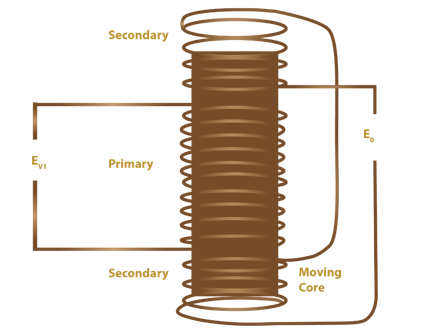
LVDT-diagram(circuit-diagram)
The generic LVDT symbol is shown in Fig.1. An LVDT transducer or LVDT is a miniature transformer having an armature core and a shaft that is free to move in a linear axis. It encompasses two symmetrical secondary coils with an equal number of turns on one primary wounded across the armature core. The secondary coils are connected in series to measure the sum of output voltage and derive the displacement in the test specimen. Movement of the shaft due to induced magnetic flux generates voltage and determines the displacement of the specimen.
LVDT Construction
In general, the structure of LVDT is similar to the inductive transformer. It comprises two sets of solenoid coils, namely primary and secondary coil lined end-to-end, covering the core. The primary coil is connected to the input AC power supply and placed at the center of the core. The secondary coil consists of two secondary windings, which are at the top and bottom of the base, with an equal number of turns wounded on a hollow cylinder. The overall behavior is evaluated in terms of linearity and robustness.
Working Principle
The core phenomenon of LVDT is mutual induction generated between primary and secondary windings. The mutually coupled circuit concept derives the input and output characteristics of LVDT. The output responses captured across secondary windings will be in the form of voltage metrics and are measured using the net induced voltage across the secondary terminals.
LVDT Working Theory (Principle)
This section provides in-depth analysis of LVDT and its operation behavior through a cylindrical core material.
At the initial stage, the cross-sectional area and dimension of the cylindrical core are measured across the core terminals. Assuming the initial parameters, theoretical analysis is used to calculate the area and moment of inertia of the core module.
A dynamic and soft iron core is placed inside the hollow cylindrical core. The position of core is measured and noted down as a null position (standard value). The LVDT system is energized by applying the excitation voltage across primary windings. Coupling voltage across the circuit is varied through the movable core, which in turn changes the flux and voltage across the secondary terminals.
The to-and-fro movement of the coil inside the outer core generates variable coupling, and the output voltage decreases based on direction (either negative or positive). The overall operating procedures are divided into three cases based on shaft movement induced EMF, and position.
LVDT Experiment and Calibrations
Assumptions and Specifications
Several abbreviations are considered to define the working procedure of LVDT and they are as follows,
EV=Voltage across the primary winding
EV1=EMF induced across secondary winding S_1
EV2=EMF induced across secondary winding S_2
Eo=Output EMF
Typical LVDT Characteristics
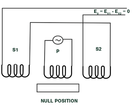
Case 1: Null Position
schematic-diagram-of-shaft-at-null-position
Fig. 2 illustrates the working procedure of LVDT at zero or null axial position. During this condition, the shaft is precisely placed at the midway of secondary windings S1and S2, which gives rise to equal flux generation and induced voltage across the secondary terminal, respectively. This position is also known as a null position.
The differentiation amongst output magnitude and output phase sequence with respect to input signal derives core movement and displacement.
The shaft placed at the null or neutral position signifies that the voltage induced across series-connected secondary windings are equal and inversely proportional to the net output voltage.
EV1= EV2 ———(1)
Eo=EV1– EV2=0 V———(2)
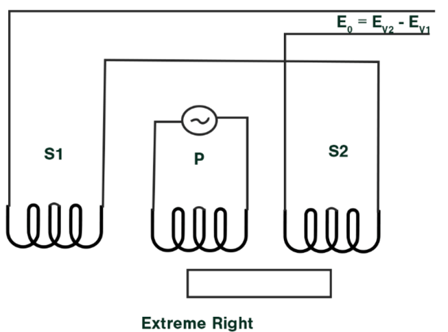
Case 2: Maximum Right Position
As shown in the following figure, when the shaft is moved towards the right side, more force is generated across S2, conversely minimum across S1.
schematic-diagram-of-shaft-at-extreme-right-position
Therefore, the induced Voltage E2 is significantly higher than E1. The equation for the resultant differential voltages are as follows,
Eo=EV2-EV1———(3)
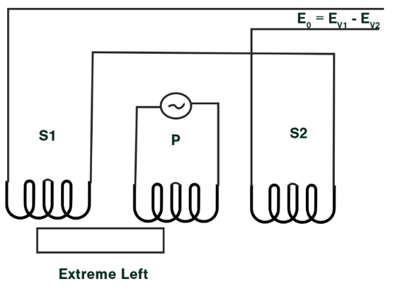
Case 3: Maximum Left Position
The below figure depicts that the shaft is more inclined towards the left side, which in turn generates high flux across S1 and induced a voltage across E1 while decreasing E2. The equation for the same is,
Eo=EV1-EV2———(4)
schematic-diagram-of-shaft-at-extreme-left-position
The resultant output of LVDT can be measured in terms of voltage, current, or frequency. This circuit can also be designed using microcontroller enabled circuits such as Arduino, PIC microcontroller, and so on.
LVDT Graph and Measurements
The following figures showcase the graphical representation of LVDT shaft variations and their effect in terms of the magnitude of differential AC output from a null position and DC output from electronics.
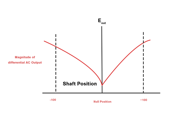
graphical-representation-of-LVDT-shaft-variations-in-terms-of-differential-output-voltage
The maximum shaft displacement value from the core position is dependent on the amplitude of the primary excitation voltage and sensitivity factor. The shaft remains at the null location until a referenced primary excitation voltage is given to the primary winding of the coil. As shown in Fig, 6, the phase shift or DC output polarity defines the shaft position for the null point. It also represents the output linearity property of the LVDT module.
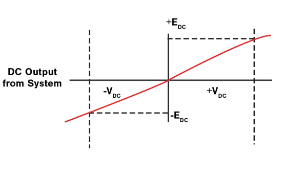
graphical-representation-of-LVDT-shaft-variations-versus-DC-output-from-electronics
LVDT Types
LVDT Sensors: It is categorized on the basis of output stage voltage parameters or a relative output current; evaluate the coil frequency as a function position or in frequency-based devices.
1). Captive Armatures: These procedures are generally used to measure long working displacement ranges. Captive alignment empowers users with low friction assemblies that avoid misalignment and ensure high reliability.
2). Unguided Armatures: Infinite resolution quality enabled unguided armature provides a no-wear design and facilitates design engineers with an unlimited resolution of measured data. This module is interfaced externally with the test specimen to be measured. It is flexible, and the user needs to guide the armature without any the interrelation between the edges.
3). Force Extended Armatures: In this mechanism, external support such as pneumatic force, spring mechanism, or electrical motors to dynamically propel armature to its utmost possible level. It is usually in slow-moving applications. This procedure eradicates the connection or interface between the test specimen and armature
Advantages
LVDT advantages are discussed below.
Nowadays, with an increased requirement of measurement units, LVDT is interfaced in the main circuit or used as an external source to measure the displacement of the object. The major advantages of leveraging LVDT circuit are as follows,
1). Smoother in operation, easy to measure and interface, and wide range displacement measurement with a range of 1.25mm to 250 mm.
2). The output value is highly sensitive and can be easily measured through the available voltage measurement devices. It reduces the requirement of the amplifier to filter or increase the output band range. The sensitivity range of the typical LVDT sensor is recorded at 40V/mm.
3). Minimal hysteresis loss that in-turn increases the reliability and offers excellent operating conditions.
4). Friction loss is approximately zero or considered as negligible due to the operation of the core is carried out inside the hollow former. This process yields actual output value with a high precision range.
5). It is capable of withstanding high wear and tear functionalities, especially during scenarios where the core is loaded with a spring or the system is under rugged operation.
6). LVDT is operated at a minimal power consumption of a range of 1w.
7). The output is obtained in terms of an electrical signal. Since most of the system input is dependent on the electrical signal, the output can be directly fed to other circuits, which reduces the requirement of other conversational elements.
8). The absence of friction enables faster dynamic response and high-core movement capability.
Disadvantages or Limitations
The limitations of LVDT are discussed below
1). Since LVDT works on the principle of the inductive transducer, a stray magnetic field is generated around the circuit. There is a requirement of an additional circuit to overcome the stray magnetic field.
2). Vibrations and temperature variations inside the electromagnetic device further inhibit the performance of the system.
Applications
The applications of LVDT include the following
1). LVDT sensors are majorly used in a myriad range of industries to measure the tension of spring, weight, displacement, and pressure, to name a few. The input factors achieved in the form of physical parameters are initially converted into displacement, followed by a corresponding electrical voltage signal.
2). It is deployed in industries to extract positive feedback from servomechanism.
3). It is used in machinery measurement tools, Aircraft industry, hydraulics, Satellite, and Industrial
Automation.
4). LVDT signal conditioner/conditioning is used to monitor and control the output waveform of the circuit.
5). The typical applications of LVDT sensors are as follows,
- Testing the strength of soil: The core of the material is engineered, softened, and manufactured using high permeability iron-nickel based alloy. Extension rod material is designed using nonmagnetic stainless steel. The voltage variation is observed during the external rod movement inside the material, which in turn generates an output pulse corresponding to displacement.
- Medical Field (Pill-making Machine): A hybrid operating mechanism of variable pitch secondary windings with a computer-controlled winding machine reduces the overall package length to stroke ratio, minimizes human error in measuring pill weight and thickness, and provides high accuracy in determining the eventual weight of medicinal powder.
- Automated Product Inspection Machine: Flat-panel displays eventually replaced the present PC and laptop monitors with high definition display systems. Small-package LVDT’s are utilized to undergo quality tests and a final check of flat-panel display dimensions.
- Aerospace: It is used to monitor flight controls, pilot control, and wheel steering mechanism.
- Robotic Cleaner: LVDT is used in leak detection systems for continuous monitoring of the fluid level. Especially systems that are submerged in nonconductive and noncorrosive fluids at ambient pressure conditions.
- Robotic Manipulator: It is used as a core part of joystick control based heavy equipment robotics.
Please refer to this link to know more about Transformer MCQ’s.
With many such applications, Linear Variable Differential Transformer is driving the futuristic displacement and measurement units in numerous business spaces. The emerging-market sectors, such as power generation, water management, and structural safety, will be likely to implement LVDT to enhance the performance and operating principles of the overall system. Furthermore, disruption of power electronic modules enables easy calibration process in LVDT and boosts the production of distance measuring instruments such as magnetostrictive transducers.