Full Subtractor and the Half subtractor both belong to the family of ‘Digital Electronics’. These are the kind of basic Logic Circuits that are designed by using ‘Logic Gates‘. Other than subtraction various circuits can be made with these gates to perform arithmetic operations. Likewise subtraction there are adder circuits to perform addition known as Half Adder and Full Adder.
The Binary Numbers consist of only two digits that are 0 and 1. If the higher number 1 should be subtracted from 0 that is the smaller number it requires Borrow digit. It is similar, to the kind of subtraction that is performed over any type of Decimal number. However, the Adder circuits that are designed by using the NOT gate which is known for complementing the input can be used as subtractors.
By using Very Large Scale Integrated circuits, the operations at the processor can speed up by performing the arithmetical operations using logic gates. Technically the subtractor is considered to be the most critical circuit among all the other digital circuits. It is mainly preferred in the processors of ‘Portable devices’. So, the design of the full subtractor must consist of the properties of compact size and to be power-efficient. This design can be made possible by using various technologies one among those is CMOS Fabrication Technology.
What is Full Subtractor?
Full Subtractor is a type of combinational circuit. This type of circuit can be built using various logic gates. The main purpose of this circuit is to perform subtraction operations on the binary numbers. Earlier the same operation can be performed by using the Half Subtractors. But in the Half Subtractor, there are two inputs applied one is minuend and the other is subtrahend. There is no option of taking the Borrow as the input from the previous stage to perform subtraction.
This has been the drawback that can be overcome in the Full Subtractor circuitry. Hence the inputs for the Full Subtractor includes minuend, subtrahend and the Borrow in. The outputs will be Difference and Borrow Out. Finally, the circuit of this subtractor consists of three inputs that produce two outputs. The circuit can be designed using the logic gates namely NOR and NAND. These are also known as ‘Universal Logic Gates’. By the use of two Half Subtractors, called a cascading technique these Full subtractors can be constructed.
The Design of this subtractor follows these steps
- Firstly, the type of operation to perform must be chosen. Then the number of inputs and outputs required is decided. In this circuit the inputs are represented as A, B, C. The outputs are represented as D and B. Where C is for the Borrow in.
- Secondly, the truth table is drawn accordingly.
- Based on the values of 1 the k-maps are plotted.
- These plottings result in the generation of Boolean expressions.
- The expressions decide the type of gates should be chosen and the circuit is constructed.
Full Subtractor Using Half Subtractors and Logic Gates
The half subtractors designed can be used in the construction of full subtractors. When the two half subtractors are cascaded together such that the Difference output generated at the first stage is connected to the second subtractor as the input.
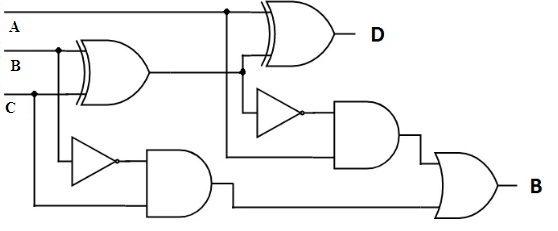
Initially, the inputs A and B are applied to the left-most circuit. Based on the functionality it generates Difference and Borrows as output. At the right circuit that is the second stage of Half subtractor Difference and the Borrow in, a bit is applied as the input. After processing, the output bit named as Difference is generated. But the borrow bit is produced in both the stages is applied to the OR gate to obtain the final Borrow out.
Similarly, the same circuit can be analyzed by using the logic gates. The subtractor designed by logic gates is described below.

Full Subtractor Circuit
The inputs A, B and C are applied through the gates. Without any complement, at both, the stages Difference output is generated. In the situation where minuend is less than the subtrahend, borrow is the necessary bit to perform subtraction. This borrows in from the first and second stages is produced by complementing the B input to the AND gates. The generated values are further provided to the OR gates. This results in the final Borrow out. The output generation is based on the applied bits at the input. For this analysis, the design of the truth table is an important step.
Truth Table and K-Map
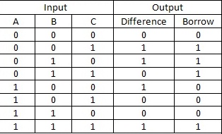
The Truth Table of this subtractor consists of the values of Minuend (A), Subtrahend (B) and the Borrow in (C) as the inputs.

Full Subtractor Truth Table
It can be noticed from the Truth Table that the output of a Difference column is similar to that of sum column output in the Full Adder circuit. It is because the complementing is used for Borrow outs. To design and to decide the type of gates and interconnections among them the plotting of K-maps is important. The output expression of difference and the sum of the adder circuit will be the same.
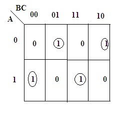
The K-map of this subtractor can be determined based on 1’s generated for the applied inputs.

full-subtractor
The expression derived for the Difference can be obtained based on the 1’s presence in the K-map is:
Difference (D)= A ⊕B⊕C
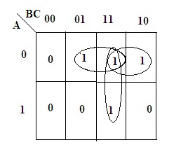
The K-map for the Borrow outcome generated for the applied input signal is

full- subtractor
The equation obtained for the Borrow analyzed from the k-map is:
Applications
In the Digital platform of electronics, there are multiple uses of these subtractors. Some of them are listed as follows:
- To perform the Arithmetic operation of subtraction that is in the ALU units these subtractors are preferred.
- The microcontrollers understand well the language of binary. Hence the operations performed by microcontrollers require the circuit of full subtractor to perform binary subtraction.
- In gadgets like calculators and other electronics devices where it involves binary numbers, these circuits are preferred.
- The systems based on Networking prefer this kind of circuitry.
Please refer to this link to know more about Combinational Logic Circuits MCQs.
Please refer to this link to know more about Binary Subtraction MCQs & Full Subtractor MCQs.
Based on the provided information it is known that full subtractor can be designed by using Universal Gates. The Design criteria remain the same for the other circuits of Binary Adders and Subtractors. The only difference will be the operation chosen. Can you describe is there any difference between the cascaded half subtractors and the parallel subtractor?