The Arm Cortex-M4F from Texas Instruments is a microcontroller that uses the Arm Cortex-M4 processor core with a DSP (Digital Signal Processing) unit. Generally, these microcontrollers are manufactured by different industries like STMicroelectronics, Silicon Labs, NXP, Infineon, and TI. So this is the first processor core of the Cortex-M that addresses digital signal control applications that need easy-to-use, efficient control & signal processing abilities like motor control, IoT, power management, healthcare, embedded audio, wellness, industrial & home automation-based applications. Thus, this article elaborates on TM4C123 IC, pinout, specifications, and applications.
What is TM4C123 IC?
The TM4C123 IC is a microcontroller unit from TI (Texas Instruments) that is an element of the Tiva C Series. This microcontroller is based on a high-performance 32-bit ARM cortex, used in different applications like stepper motors control, HVAC control, factory automation, remote monitoring, etc. So this TIVA launch pad includes up to 80MHz an in-built processor CLK frequency with an FPU (floating-point unit). It can also have an NVIC (nested vector interrupt controller). The Cortex-M4F processor supports the tail chaining functionality. Thus, this MCU uses debugging interfaces like JTAG & SWD for programming & debugging purposes.
How TM4C123 IC Works?
The TM4C123 IC works as a programmable and small computer that controls different electronic devices by simply processing digital signals and communicating with external peripherals using its I/O pins. So this microcontroller executes stored code within its memory to handle various tasks like motor control, data acquisition, and communication protocols such as UART, SPI & I2C in a single IC. It is a very popular choice to use in embedded systems applications because of its broad range of incorporated peripherals & powerful processing abilities.
Pin Configuration:
TM4C123 IC pin configuration is shown below. So it includes 64 pins which are explained below.
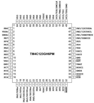
TM4C123 IC Pin Configuration
PORT-A (PA0 – PA7): These are port-A pins like pins 17 to pins 24 like UORx, UOTx, SSIOClk, SSIOFss, SSIORx, SSIOTx, PA6, and PA7.
PORT-B (PB0- PB7): These are port-B pins like pins 1, 4, 45, 46, 47 & 48 (PB6, PB7, USBOID, USBOVBUS, I2COSCL, and I2COSDA.
PORT-C (PC0 – PC7): These are port-C pins like pins 13, 14, 15, 16, 49, 50, 51, and 52 (PC7, PC6, PC5, PC4, TDO or SWO, TDI, TMS or SWDIO, TCK or SWCLK).
PORT-D (PD0 – PD7): These are port-D pins like pins PD1 to PD7.
PORT-E (PE0 – PE5): These are port-E pins which include pins PE0 to PE5.
PORT-F (PF0-PF4): These are port-F pins like pins PF0 to PF4.
Pin-2 (VDDA): It is an analog supply pin of the microcontroller.
Pin-11, 26, 41 & 54 (VDD): These are voltage supply pins of microcontroller.
Pin-12, 27, 39 & 55 (GND): These are ground pins of IC.
Pin-25 (VDDC): It is the internal core voltage pin of the IC.
Pin-32(WAKE): This pin wakes up the launch pad from a low power condition.
Pin-33 (HIB): This pin is used for different functions like the microcontroller’s output control.
Pin-34 & 36 (XOSCO & XOSC1): These pins are utilized to connect an outside crystal.
Pin-35 (GNDX): This pin indicates a GND for an o/p (or) voltage o/p.
Pin-37 (VBAT): It is a power supply pin that gets power supply from a backup & the system power supply.
Pin-38 (RST): This is a reset pin that receives a reset signal & restarts the microcontroller.
Pin-40 & 41 (OSC0 & OSC1): These are oscillator pins of the microcontroller IC.
Pin-56 (VDDC): This is a power pin that provides a voltage supply to the microcontroller.
Features & Specifications:
The features and specifications of TM4C123 IC include the following.
- TM4C123 is a Tiva C Series LaunchPad from Texas Instruments.
- This development board includes 64 pins.
- It has an 80 MHz speed.
- Its flash memory is 256 KB and SRAM is 32 KB.
- Peripherals are; 8 UARTs, 4 SPI & 4 I2C.
- It includes two QEI (Quadrature Encoder Inputs), a 24-bit SysTick timer & 43- GPIO pins.
- Analog inputs are; 12-ADC channels & 12-bit ADC
- It has 16-PWM outputs.
- It has general purpose timers – 6 where each has two 16-bit PWM outputs (or) 32-bit PWM output.
- Communication used is USB & CAN.
- Its operating voltage is 3.3V.
- The power supply is possible through a USB (or) external 5V supply.
- The debugger used is ICDI (On-board In-Circuit Debug Interface)
- It is well-matched with different IDEs like Keil, IAR & Code Composer Studio.
- Its temperature ranges from -40°C to 85°C
- It supports extensive libraries & tools with TivaWare.
TM4C123G Launch Pad Components
TM4C123G launch pad includes different components like an OnBoard microcontroller, push buttons & onboard LEDs which are explained below.
The TM4C123G launch pad includes two onboard chips like debugger &the microcontroller. So the debugger placed on the board will be SWD or JTAG whereas the microcontroller chip placed on the board will be TM4C123G.
This launch pad includes two onboard push buttons that are internally connected to the GPIO pins. So a toggle switch is utilized as a power switch whereas the remaining push button can be utilized to restart or reset the program execution, so it is loaded already on the board. The push-button switch like SW1 can be connected to the PF0 GPIO pin whereas the push-button switch like SW2 is connected to the PF4 GPIO pin.
This launch pad board includes tri-color LEDs, one tri-color LED is available on the TIVA launch pad that is connected internally to the GPIO pins in the F port. Once the enabled LED shows the enabled pin’s color. In addition, there is a green color power LED on the board which tells the user when the board is turned on.
TM4C123 IC Architecture
TM4C123 IC architecture includes different blocks which are explained below.
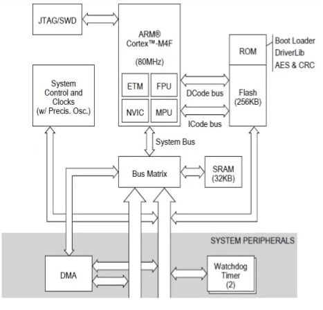
Buses
This launch pad includes two buses APB or Advanced Peripheral Bus & AHB or Advanced High-Performance Bus. So the AHB bus is very fast as compared to the APB. It also allows a single CLK cycle to the peripherals. The APB bus access time is 2 clock cycles minimum.
Memory
- TM4C123 IC includes 256 kb flash memory.
- It has single-cycle SRAM – 32 kb with internal loaded ROM with TivaWare software.
- It has EEPROM – 2 kb which is quick & saves board space.
Serial Communication Peripherals
This launch pad can also have USB 2.0 (HOST/ OTG/ Device), 6 I2C, 8 UART ports with IrDA, 9-bit & ISO7816 ports, four SPI microwire (o) TI synchronous serial interface and two CAN modules.
ADC Channels
This launch pad microcontroller includes two ADC channels which transmit 12-analog input channels. So this channel can also have four sample sequencers as a part of every ADC module to give different sampling rates & sampling averaging features.
Memory Protection Unit
This launch pad includes an in-built feature to generate a memory management fault on wrong access to the section.
Timers
- The timers of the launch pad include two watchdog timers through separate CLKs.
- One SysTick timer includes 24-bit high-speed RTOS & one more timer.
- It includes six 32-bit & 64-bit general-purpose timers.
PWM Channels
TM4C123GH6PM microcontroller includes two PWM Channels where each PWM channel includes 4 control blocks & 4 generator blocks. In addition, every PWM generator gives two PWM output signals. Thus, we can obtain complete 16 PWM signals using the TM4C123 Tiva Launchpad.
32-channel DMA
This launch pad includes two interrupt-enabled priority levels with 8, 16 & 32-bit data sizes.
NVIC (Nested Vector Interrupt Controller)
This launch pad has an in-built nested vector interrupt controller that includes seven exceptions & 71 interrupts with 8-programmable priority levels. So these priority levels choose the interrupt priority described by the user operator and have lower priority always as compared to the programmer-defined exceptions.
16×2 LCD Display Interfacing with TM4C123G TIVA C Series LaunchPad
The text below shows the interfacing of the 16×2 LCD with the TM4C123G TIVA C series launch pad. This interfacing displays useful information and sensor data. Users utilize the 16×2 LCD, a low-cost display module, in public PCOs and other electronics projects. This module proves very handy for displaying debugging information or data in many applications. Therefore, developers can display ADC values and voltage levels on the LCD. They can change these ADC values by connecting a potentiometer.
The required components to make this interfacing mainly include; a TIVA TM4C Launch Pad, 16×2 Dot matrix LCD, and connecting wires.
The 16×2 LCD includes 16 Columns & 2 Rows and together it forms 32 boxes. So a single box includes 40 pixels with 5 Rows & 8 columns in a matrix order. So these 40 pixels can form one character together. Likewise, 32 characters can be displayed by using all these boxes.
The LCD includes 16 pins total which can be separated into four groups.
- Pins 1, 2 & 3 of LCD are known as source pins where these pins can source the power & contrast level mainly for the display.
- Pins 4, 5 & 6 are control pins that set or control the registers within the LCD interfacing IC.
- Pins 7 to 14 are data or command pins which provide the data to display on the LCD.
- Pins 15 &16 are LED pins that are useful in glowing the LCD backlight if needed.
ADC within TIVA LaunchPad
The potentiometer gives analog output thus it cannot be connected to the Launchpad’s digital pins. Thus Analog (or) ADC pins of the microcontroller unit are utilized to interface any kind of sensor whose o/p is analog within nature. Here, TIVA TM4C includes two ADC channels including 12-bit output. So the analog values of the sensor (or) potentiometer can be easily mapped between 0 to 2^12 to change them into digital values.
Connections
One main limitation of LCD interfacing with a launch pad is its operating voltages. So the LCD operating voltage is +5Volts while the Launchpad works with 3.6V only. The data pin of the LCD interface has a 2.7V to 5.5V wide operating voltage. So we have to worry about only the Vdd pin of the LCD whenever the data pins work even with 3.6Volts.
By default the launch pad does not include a +5V pin, thus an external power supply must be utilized to make the display work like a power supply using an Arduino board (or) from a 7805 voltage regulator IC. Confirm to connect the GND of the power supply with the GND of the TIVA board.
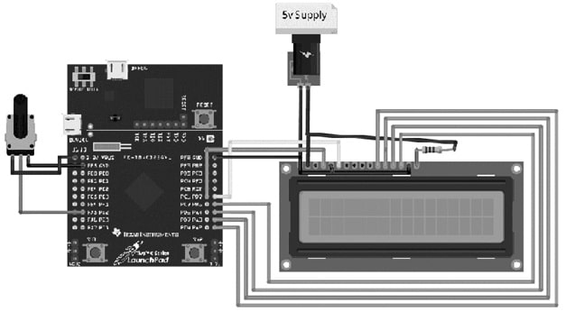
LCD Display Interfacing with TM4C123G Launch Pad
The connections of this interfacing follow as;
- Connect the Vss pin of the LCD to the GND pin of the TIVA Launchpad
- The power supply of the TIVA Launchpad connects to the Vdd pin of the LCD.
- Connect the Rs pin of the LCD to Pin PC_6 of the TIVA Launchpad.
- Connect the R/W pin of the LCD to the GND pin of the TIVA Launchpad.
- The Enable pin of the LCD connects to Pin PB_7 of the TIVA.
- Connect the D4 pin of LCD to the Pin PA_2 of Launch pad.
- Connect the D5 pin of LCD to the Pin PA_3 of TIVA
- The D6 pin of LCD is connected to the Pin PA_4 of TIVA
- Connect the D7 pin of LCD to the Pin PB_6 of TIVAboard.
- Connect the Potentiometer output to any PE2 analog pin to display the values of the potentiometer on display.
Code
The required code for this interfacing is shown below.
#include
#define RS PC_6, EN PB_7, D4 PA_2, D5 PA_3, D6 PA_4, D7 PB_6 and sensorPin PE_2;
int sensorValue ;
float voltages;
LiquidCrystal lcd(RS, EN, D4, D5, D6, D7);
void setup() {
lcd.begin(16, 2);
lcd.setCursor(0, 0);
lcd.print(“CircuitDigest”);
delay(2000);
}
void loop() {
sensorValue = analogRead(sensorPin);
lcd.setCursor(0, 0);
lcd.print(“ADC value:”);
lcd.setCursor(10, 0);
lcd.print(sensorValue);
lcd.setCursor(0, 1);
lcd.print(“Voltages:”);
voltages=(sensorValue*3.3)/4096;
lcd.setCursor(10, 1);
lcd.print(voltages);
delay(1000);
}
Working
After you make the connections and set the code, connect the TIVA launch pad to the computer and upload the code onto the board. Once you upload the code, you should see the LCD. Now, turn the potentiometer to change the ADC value and you will observe that the equivalent voltage value can also change.
Advantages & Disadvantages
The advantages of TM4C123 IC include the following.
- The TM4C123G is a low-cost evaluation platform mainly for Arm Cortex-M4F microcontrollers.
- It is a 32-bit high-performance ARM cortex M4 microcontroller with a wide range of peripherals.
- This launch pad includes an in-built processor with up to 80MHz clock frequency with a FPU (floating-point unit)
- This LaunchPad is used for working with C series-based microcontrollers that provide 32-bit performance with up to 180MHz operating speed.
- This microcontroller’s timer modules can be utilized to measure either analog & digital signal frequency.
- It is very fast as compared to msp430.
The disadvantages of TM4C123 IC include the following.
- TM4C123 IC relies on exact timing to perform instructions & tasks otherwise they may cause malfunctions & errors.
- They need a stable power supply to work correctly.
- They produce heat during operation, and extreme heat can harm the device.
- These launch pads can be affected by EMI (electromagnetic interference) and RFI (radio frequency interference) from different electronic devices which cause errors & malfunctions.
- Launchpads can be susceptible to security breaches like data theft, malware attacks & unauthorized access.
Applications
The applications of TM4C123 IC include the following.
- This TM4C123G LaunchPad is a flexible platform for developing applications like robotics, IoT, embedded systems, etc.
- This is a low-cost based evaluation platform used for Arm Cortex-M4F MCUs.
- This simple wired serial communication protocol transmits data serially between two devices in embedded systems applications.
- Industrial applications, such as electronic point-of-sale machines, remote monitoring, network appliances, network switches, test & measurement equipment, gaming equipment, factory automation, HVAC & building control, motion control, fire safety, security, and transportation, utilize this launch pad.
- These microcontrollers can communicate with outside devices (or) with each other above the
- UART serial communication protocol.
- This IC is designed to be used in electronic systems to control specific tasks.
Please refer to this link for the TM4C123 IC Datasheet.
Thus, this is an overview of TM4C123 IC, pinout, features, specifications, interfacing, and its applications. This MCU is based on the Arm Cortex-M4F from Texas Instruments and is a part of the Tiva C Series. This microcontroller includes a USB 2.0 interface that can be utilized for different applications like stepper motor controlling and many more. Here is a question for you, what is HC-SR04?