TIP (Texas Instruments Power) transistor is a series of BJTs manufactured by TI (Texas Instruments). This series was launched in the 1960s, and these transistors are still used because of their durability, ease of use, and simplicity. So, TIP transistors are standard-type bipolar junction transistors that are used mainly for medium power-based applications. These are designated with A, B, and C to designate increasing CB and CE breakdown voltage ratings. Thus, the examples of TIP series transistors are; TIP120, TIP122, TIP127, TIP35, TIP3055, TIP31C, TIP32C, TIP35C, TIP36C, TIP41C, TIP42C, etc. This article provides an overview of the TIP35 transistor, pin-out, specifications, and its uses.
What is TIP35 Transistor?
The TIP35 is an NPN power transistor with through-hole complementary from STMicroelectronics which is available in TO 247 package. The TIP35 transistor is manufactured within planar technology through a base island layout. So the resulting transistors show excellent high gain performance fixed with extremely low saturation voltage. So, this silicon transistor is used mainly for general-purpose switching and power amplification. This transistor is used commonly in audio amplifiers & inverters.
While looking for a suitable transistor for your application based on a few factors, it is very important to look into a few points on How to Select a Transistor.
How TIP35 Transistor Works?
A TIP35 NPN power transistor works by controlling a large current supply at its collector with a smaller current provided to its base terminal. So, this transistor works as a current amplifier; whenever a small voltage is provided to the base terminal relative to the emitter terminal, then it allows a huge current flow from the collector terminal to the emitter terminal. Thus, it is used in high-power applications like audio amplification, power switching, or motor control because of its high current handling ability.
Pin Configuration:
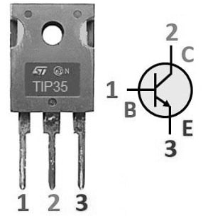
The pin configuration of the TIP35 transistor is shown below. This transistor includes three terminals which are discussed below.

TIP35 Transistor Pin Configuration
- Pin-1 (Base): The base terminal achieves the transistor biasing and it impulses the transistor state.
- Pin-2 (Emitter): This terminal emits the charge carriers.
- Pin-3 (Collector): This terminal collects the charge carriers from the emitter and is connected to the load.
Features & Specifications:
The features & specifications of the TIP35 transistor include the following.
- TIP35 is an NPN power transistor.
- The series of TIP35C or TIP36C transistors are designed with planar technology and a base island layout which results in higher gain performance.
- This transistor includes three pins.
- It is available in the TO 247 package.
- Its maximum collector DC is 25Amps.
- This transistor’s collector-to-base voltage is 100V.
- Collector to emitter voltage is 100V.
- The emitter to base voltage is 5V.
- Its maximum frequency is 3 MHz.
- Power dissipation is 125 watts.
- Operating temperature ranges from -65°C to 150°C.
Equivalents & Complementary:
Equivalent TIP35 transistors are; TIP101, TIP100, TIP105, TIP102, TIP106, TIP107, TIP36C, TIP110, etc. So the complementary transistor is the TIP36 PNP transistor.
Replacing a suitable transistor in any circuit based on requirement is very important. So as to know how to replace it, please refer to this; Replacing Transistors in Electronic Circuits: Factors and Considerations.
Universal Battery Charger Circuit with TIP35 Transistor
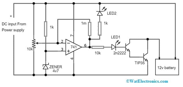
The universal battery charger circuit with a TIP35 transistor is shown below. This circuit explains how to charge all kinds of batteries irrespective of the current capacity (or) the AH level. So this battery charger circuit is used to charge any kind of battery without worrying about safety and compatibility issues.
Thus, the required components to make this universal battery charger circuit mainly include; 741 IC, transistors 2N2222 & TIP35, resistors like 1K, 1M & 10k, 10k POT, 4V7 zener diode, RED LED & 12V 200aH battery.

Universal Battery Charger Circuit with TIP35 Transistor
Working
This 12V universal simple automatic battery charger circuit includes an op-amp accountable for governing the state of the battery & triggering the LED indicator when the charging process is finished. So this circuit has a three-stage resistive divider that allows the reference voltage mainly for the op-amps. Once the current supply falls under the half ampere the connected battery will cut off.
So this circuit begins to oscillate by working the transistor that switches current to the light emitting diode which indicates the glowing & indicating the complete charge range of the battery. Here bridge rectifier’s input power supply may need to be >10 Amp. So filter capacitor in this circuit can be connected onto the plate (or) twisted within the cabinet with a pair of plastic seals and connected in parallel with the +ve and -ve terminals of the rectifier bridge.
Do not attach the battery but first provide 14.4Volts from the DC input & adjust the 10K preset, thus the green LED lights & the red LED will turn OFF. After that, the 12V 200AH battery must be connected, then the input will be switched on & the battery starts charging. So the red color LED will glow when the battery starts charging. Once it attains 14.4V, then the red LED turns OFF & the green color LED will light up which indicates the completely charged condition of the battery.
Thus, this automatic universal battery charger circuit is an essential tool that can charge any type of battery securely and efficiently to provide a power supply to their devices. The convenience & versatility it provides are unmatched, and it has the potential to extensively decrease electronic waste by prolonging the lifetime of our batteries.
Difference between TIP35 and TIP3055
The difference between TIP35 and TIP3055 transistors includes the following.
|
TIP35 |
TIP3055 |
| It is available in the TO−247 package. | It is available in the TO-218 package. |
| TIP35 transistor handles up to 40V of electrical power. | TIP3055 transistor handles up to 60V of electrical power. |
| It handles up to 25 amps of current. | This transistor handles up to 15 amps of current. |
| It is used commonly in electronic circuits that require high power like motor controls, amplifiers, etc. | This transistor is used in circuits that require medium power, like audio amplifiers & power supplies. |
| Its transition frequency is 3 MHz. | Its transition frequency is 2.5 MHz. |
| Power dissipation is 125 W. | Power dissipation is 115W. |
| DC gain is 15 hFE. | DC gain is 20 to 100 hFE. |
Connecting a base resistor to the base terminal of the transistor is mandatory to avoid it being damaged. So, please refer to this link for; Choosing Base Resistance for Transistors in Electronic Circuits.
Advantages & Disadvantages
The advantages of the TIP35 transistor include the following.
- This IC has excellent high-gain performance.
- It has an extremely low saturation voltage.
- This IC is designed for power amplification & switching.
- It is manufactured within planar technology through a base island layout.
- Pb-free packages are accessible.
The disadvantages of the TIP35 transistor include the following.
- This transistor has average junction temperature & second breakdown
- The TIP35 transistor dissipates more current as heat within a class-A amplifier circuit. So this results in less conversion efficiency.
- Exceeding the highest ratings can harm the transistor, so it can affect the reliability & functionality.
- This transistor can malfunction or fail due to physical damage, overheating, incorrect circuit design, and manufacturing defects.
- Its power handling capability is limited through its average junction temperature & breakdown secure operating area curves.
Applications
The applications of the TIP35 transistor include the following.
- The TIP35 NPN transistor can be utilized as an audio amplifier and also for general-purpose applications.
- It can be used for converters, power amplifiers, and switching regulators
- This is used widely in the motor drive field because of its characteristics of high current & high power.
- It can be utilized at the output side of the power inverter to change DC to AC voltage.
- This type of transistor is used in inverters & audile amplifier’s output stages wherever they are coupled within push-pull through a corresponding type of power transistor.
- This transistor can be used within different industrial schemes.
- It is used within automotive body electronics, power trains, LED lighting, security, safety, vehicle electrification, ADAS, etc.
- This transistor is used within 5G, cloud power telecom infrastructure & server power.
- It is used in RF power amplifiers, audio amplifiers, motor control circuits, power supplies, linear regulators, high-power linear applications, etc.
- It is used within industrial control systems that need high power-handling abilities.
- This is used in high-power consumer electronics audio equipment and power supplies.
Please refer to this link for the TIP35 Transistor Datasheet.
Thus, this is an overview of the TIP35 power transistor, pin-out, features, specifications, circuit, working, pros, cons, and applications. So this power transistor uses planar technology including a base island layout. So the resulting transistors will show exceptional high gain performance connected with extremely low saturation voltage. Thus, it is an NPN type of reliable silicon transistor that is used in common amplification & switching purposes. Here is a question for you, what is a TIP105 transistor?