A voltage sensor is a module or device used to monitor and estimate the voltage for the device (or) system. This sensor’s input is the voltage whereas the output is a current, an audible signal, or an analog voltage signal. So these sensors can measure the voltage in different methods from measuring higher voltages to noticing low current levels in power systems and industrial controls. These sensors are available in a VSR (voltage-sensitive resistor) and op-amp (operational amplifier). Thus, the VSR type is used within electronic circuits wherever small changes in voltage need to be detected like solar panel output or battery life. Op-amp type voltage sensor is used for different tasks like controlling LEDs or driving motors which are frequently found in Arduino boards. Thus, this article provides an overview of the B25 Voltage Sensor, pinout, specifications, and its applications.
What is a B25 Voltage Sensor?
A B25 is a simple and low-cost voltage sensor module that utilizes a resistive voltage divider design to decrease the input voltage by five times. So this module allows 25V maximum input voltage while using the highest 5V voltage on the side of the ADC in the module. These voltage sensors are based on the resistive voltage divider design principle, which contains a resistor that works like a sensing element. So the voltage divider circuit can be designed by separating the voltage into two resistors; a reference voltage and a variable resistor. Thus, whenever we apply voltage supply to this circuit the resistance utilized within the circuit decides the o/p voltage.
B25 Voltage Sensor Working
The B25 0 to 25V voltage sensor module works by using a resistive voltage divider to reduce the input voltage by a factor of five. So this allows the sensor module to examine voltages that are high as compared to the analog i/p of a microcontroller. If the analog input range of the microcontroller range is from 0-5V thus the B25 voltage sensor module measures up to 25V voltage.
Pin Configuration:
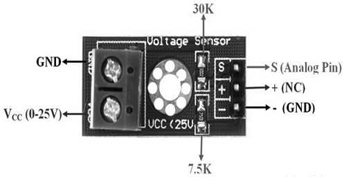
The pin configuration of the B25 voltage sensor is shown below. This sensor includes five pins which are explained below.

B25 Voltage Sensor Pin Configuration
- Pin-1 (VCC): This is the positive terminal of the IC where the voltage ranges from 0 to 25V.
- Pin-2 & 5 (GND): These are the negative terminals of the external voltage source of the IC.
- Pin- 3 (S): It is an analog pin that needs to be connected to the microcontroller’s analog pin.
- Pin-4 (NC): It is a not connected pin.
Features & Specifications:
The features and specifications of the B25 voltage sensor include the following.
- B25 is a voltage detection sensor module.
- It includes five pins.
- It works based on the design principle of the resistive voltage divider.
- Input voltage ranges from 0 to 25 volts.
- The voltage detection range is from 0.02445 to 25.
- The analog voltage resolution is 0.00489 volts.
- Its dimensions are; 4 × 3 × 2 cm.
Equivalents & Other Modules:
Equivalent B25 voltage sensor modules include; ZMPT101B, F031-06, MH 25V, ET5204, MAX471, HMC5883L, etc. So other modules include; the LDR sensor module, IR sensor module, DS3231 RTC module, TP4056A Li-ion battery charging/discharging module, TMC2209 stepper motor driver module, A4988 stepper motor driver module, DRV8825 stepper motor driver module, NEO-6MV2 GPS module, EM18 – RFID reader module, joystick module, soil moisture sensor, ADXL335 accelerometer module, etc.
B25 Voltage Sensor Internal Circuit
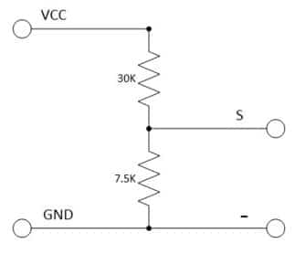
The B25 voltage sensor internal circuit diagram is shown below. This circuit uses two resistors (R1 & R2) within the circuit. So the R1 resistor is closest to the input voltage like 30 KΩ whereas the R2 resistor is closest to GND with 7.5 KΩ. The two resistors are connected in series in the following circuit whereas the signal pin can be connected between them.

Internal Circuit
So the voltage divided voltage will be the voltage drop across the second resistor. This signal can be broken out to an S header pin. Thus this circuit separates the input voltage through a factor of 5. Thus, this voltage sensor helps in measuring voltages < 25 V with an Arduino.
The voltage sensor reading is very easy with the following voltage divider equation. So this equation assumes that you know three main values of the above divider circuit like the input voltage (Vin) and two resistor values like R1 and R2. Thus the output voltage or Vout can be measured using these values.
Vout = Vin (R2/ R1 + R2)
Here the output voltage or Vout can be measured from the above voltage divider circuit with ADC of Arduino. So, we don’t know the Vin value. If we arrange the above ‘Vout’ equation, we can get the ‘Vin’ equation.
Vin =Vout (R1 + R2/ R2)
Thus, the above input voltage (Vin) equation shows that the output voltage is divided by the fraction of the resistance of the second resistor over the whole resistance (R1 + R2) within the circuit.
B25 Voltage Sensor Interfacing with Arduino
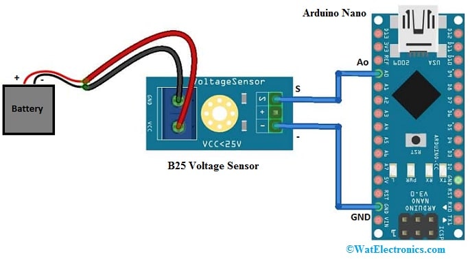
The B25 voltage sensor interfacing with Arduino is shown below. The below interface is used to measure DC Voltages. In the following interface, first, we will connect the B25 voltage sensor module with Arduino Nano board to measure the voltages for different Batteries. Thus, the output voltage can be observed on the serial monitor.
So the required components to make this interfacing mainly include a battery, a B25 voltage sensor, and an Arduino board. Thus, connect this interfacing circuit as per the diagram shown below.

B25 Voltage Sensor Interfacing with Arduino
Thus, the connections of this interfacing follow as;
- Connect the Signal (S) pin of the voltage regulator to the A0 pin of the Arduino nano board.
- Connect the negative (-) pin of the voltage regulator to the GND pin of the Arduino board.
- Thus finally, connect the battery’s positive and negative terminals to the VCC and GND terminals of the voltage sensor module.
Code
The required code for the B25 voltage sensor interfacing with Arduino Nano is shown below.
// Define analog input
#define ANALOG_IN_PIN A0
// Floats for ADC voltage & Input voltage
float adc_voltage = 0.0;
float in_voltage = 0.0;
// Floats for resistor values in divider (in ohms)
float R1 = 30000.0;
float R2 = 7500.0;
// Float for Reference Voltage
float ref_voltage = 5.0;
// Integer for ADC value
int adc_value = 0;
void setup()
{
// Setup Serial Monitor
Serial.begin(9600);
Serial.println(“DC Voltage Test”);
}
void loop(){
// Read the Analog Input
adc_value = analogRead(ANALOG_IN_PIN);
// Determine voltage at ADC input
adc_voltage = (adc_value * ref_voltage) / 1024.0;
// Calculate voltage at divider input
in_voltage = adc_voltage / (R2/(R1+R2)) ;
// Print results to Serial Monitor to 2 decimal places
Serial.print(“Input Voltage = “);
Serial.println(in_voltage, 2);
// Short delay
delay(500);
}
Working
To test the B25 voltage sensor working, here three different types of batteries and used, and the voltage supply on the serial monitor. So initially, this sensor was tested with a common 3.7Volts lithium-ion battery. The correct reading result can be shown on the serial monitor according to the Battery’s voltage. Likewise, this sensor testing can be done with a 9V battery. Thus, this voltage sensor detects the reading of approximately 5V whenever it is tested with a 3S discharged Lithium-Ion battery.
Thus, a 0-25V DC voltage sensor module with Arduino interfacing was successfully demonstrated to measure different battery voltages. So this mechanism allows up to 25V with a 5V analog pin precise measurements.
Advantages and Disadvantages
The advantages of the B25 voltage sensor include the following.
- It doesn’t need external components/
- It is a small, inexpensive, and simply available sensor.
- This sensor can be used easily with microcontrollers.
- It reduces five times of the voltage supply of the i/p terminal connection.
- Voltage sensors have many advantages, including:
- These are highly accurate and detect even small changes within voltage levels.
- These sensors are cheaper.
- They avoid accidents by noticing live circuits & voltage fluctuations to protect people from shocks.
- These are efficient.
- They can monitor equipment & systems continuously by providing instantaneous data.
- These are lighter, smaller, and eco-friendly
The disadvantages of the B25 voltage sensor include the following.
- These sensors have a non-linear response thus output doesn’t differ proportionally across the whole range of values.
- They consume more power.
- These sensors are more vulnerable to noise interference because of low voltage levels.
- It needs four wires where two wires for voltage supply and two wires for output voltage.
- Device malfunctions can result in false negatives.
Applications
The applications of the B25 voltage sensor include the following.
- This voltage sensor identifies the electricity breakdown.
- It is used for load sensing and maintains the temperature in control.
- This sensor controls the power demand and discovers faults, thus it can also be used as protective switching.
- This sensor is used to control temperature, energy management, and motor overload.
- It is used in data acquisition and building control systems.
- This sensor allows the consumer to monitor voltages that are higher than the analog input of microcontrollers can sense.
- This sensor module can be interfaced with an Arduino board to measure up to 25 volts of voltage.
- This sensor module is designed mainly for electronic circuit designers & integrators.
Please refer to this link for the B25 voltage sensor Datasheet.
Thus, this is an overview of the B25 voltage sensor, pinout, features, specifications, interfacing, pros, cons, and its uses. So this sensor module works based on the principles of resistive voltage divider design. Thus it is capable of decreasing five times the voltage supply of the input terminal connection. This sensor is used to find out the range of voltage present within any equipment. So it is responsible for deciding the existing electrical charge within each device. Thus, here is a question for you, what is ZMPT101B?