Generally, semiconductor devices are indicated with special number coding according to their specifications. So these components have a special symbolic number including an alphanumeric coding to represent the material characteristics and other parameters. The semiconductor devices and components include a minimum of two letters & three numbers or three letters & two numbers. So, the example of two letters & three numbers is BF194, used for consumer equipment (or) entertainment purposes. In contrast, the semiconductor device with three letters & two numbers is BFX 63 which is primarily used for industrial or professional. This article discusses an overview of the BF194 transistor, pinout, specifications, working, and its applications.
What is BF194 Transistor?
The BF194 is a BJT with an NPN-type configuration which means this transistor includes a positively charged layer between two negatively charged layers. This transistor includes three terminals; base, an emitter & collector, and is enclosed within a TO-92 and SOT-25 package. The TO-92 package makes it simple to handle & suitable for a variety of applications whereas the SOT-25 package is a half octagon including a staggered center pin.
This transistor has an arrow symbol that indicates from the base terminal into the emitter terminal so that the current supplies from the collector to the emitter terminal. These types of transistors are used widely for signal processing & audio amplification due to their high gain, excellent linearity, and low noise. The maximum power dissipation of this transistor is 350mW.
This is a high-performance and versatile transistor, used in a wide range of applications. Its 350mW max power dissipation provides high gain, low noise & excellent linearity which make it perfect for signal processing and audio amplification. Its low cost and compact size will make this transistor an attractive option mainly for beginners & professionals. This transistor’s maximum collector current is 50mA & a max CE voltage of 20Volts makes it an efficient and reliable choice in a variety of applications.
While looking for a suitable transistor for your application based on a few factors, it is very important to look into a few points on How to Select a Transistor.
Transistor can also be interfaced with a microcontroller. To know more on it click on How to interface a transistor to microcontroller.
BF194 Transistor Pin Configuration:
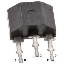
The pin configuration of the BF194 transistor is shown below. This transistor includes three terminals which are discussed below.

BF194 Transistor Pin Configuration
- Pin-1 (Emitter): Current drains out throughout this terminal.
- Pin-2 (Base): The base terminal controls the transistor biasing. It transfers charge carriers from the emitter terminal to the collector minimum loss.
- Pin-3 (Collector): Current flows in throughout this terminal. It gathers all the charge carriers.
Features & Specifications:
The features and specifications of the BF194 transistor include the following.
- It is a bipolar junction transistor.
- It includes three terminals.
- Transistor polarity is NPN, available in the TO-92 transistor.
- The material of the transistor is Silicon.
- The minimum collector power dissipation or PC is 0.25W.
- The collector to base voltage minimum or VCB is 30V.
- Collector to emitter voltage or VCE minimum is 20V.
- Maximum collector current or IC is 0.03Amps.
- The maximum operating junction temperature or TJ is 125°Centigrade.
- The emitter to base voltage or VEB maximum is 5V.
- The forward current transfer ratio or hFE value is 67.
- The transition frequency or FT is 260MHz.
- Collector capacitance or CC is 1.9pF.
Equivalent & Complementary Transistors
Equivalent BF194 transistors are; BFY50, BFY51, BF195, BF196, BF197, BC158, BC159, BC157, BCX35, BD539, TIP29C, BU407, BUP30, 2N6099, D44C10, BD241C & BD743. Complementary BF194 transistors are; BFR14, BFX88 and BFR49.
Replacing a suitable transistor in any circuit based on requirement is very important. To know how to replace it, please refer to this; Replacing Transistors in Electronic Circuits: Factors and Considerations.
Metal Detector Circuit with BF194 Transistor
Here a metal detector circuit is designed with a BF194 transistor to hunt hidden treasure, detect metallic objects like iron ore, metal coins, silver, gold, and aluminum, and also to detect concealed wiring and buried cable, etc.
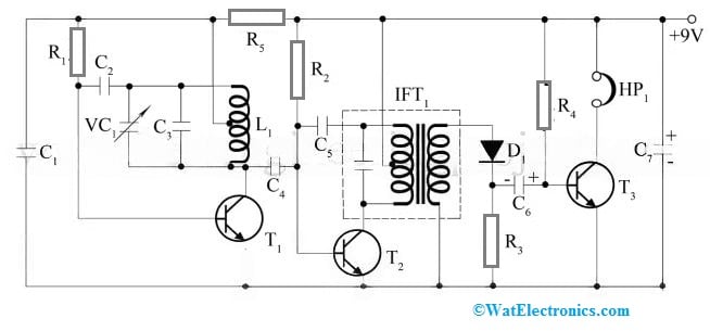
The required components to make this circuit mainly include; resistors like; 1 MΩ, 10 KΩ and 2.2 KΩ, ceramic disc capacitors like; 0.5 µF, 20 pF, 390 pF, 120 pF, Electrolytic capacitors like; 5 µF, 12V and 100 µF, 16V, 250 pF VC1, transistors like BF194 (or) 2N2926, BF195 (or) 2N2926, OA79 germanium diode, 24 SWG to 36 SWG 26 turns of wire, IF transformer and HP1 headphone. Connect this circuit as per the circuit given below.

Metal Detector Circuit
Working
This metal detector circuit is designed with an IF transformer, three NPN transistors, a few passive components, and a search coil. This circuit includes two oscillators which are designed with two transistors; T1 & T2. So, one oscillator works at 455 KHz whereas the other oscillator works at 452 KHz slighter lower frequency. The IF transformer in the circuit uses an oscillator, and an L1 coil, and the search coil is used by another oscillator.
The C4 capacitor in the above circuit is used as a coupling capacitor which helps in connecting two oscillators. Whenever any metal is placed near to metal detector circuit then 3 KHz of a beat frequency is generated which is amplified by a T3 transistor & loud sound can be heard throughout the headphones. So, a VC1 variable capacitor in the circuit is utilized as a tuned capacitor. A search coil includes 26 wire turns and is center-tapped. The wire gauge can be preferred from 24 SWG to 36 SWG.
This circuit operation is very simple. So a metallic object is placed near the search coil of the circuit & turns ON the device. Here, the VC1 gang capacitor can be adjusted until the beat note is listened to loudly & clearly throughout the headphones. So this circuit is capable of placing metal buried up to 30cm within the earth, supplied it is there in abundance. But there is a small number of metal buries, thus it must be capable of detecting it up to 15cm depth.
FM Radio Transmitter Circuit
FM radio transmitter is a high quality, low cost, and high range circuit used to control both power & tone with frequency control mutually. This transmitter’s output power is approximately 200mW. By using this transmitter circuit, you can arrange a small radio network through your neighborhoods.
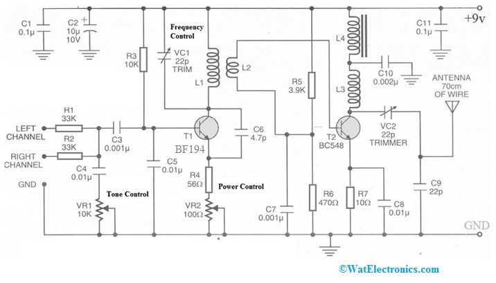
The required components to make this simple circuit mainly include; BF194 or BF494, BC548, capacitors 0.001uF, 0.01uF, 0.1uF, 0.002uF, 22pF, 4.7pF and 10micoF 10V, 22pF Trimmer variable capacitors, resistors like; 3.9k-ohm, 10k-ohm, 33k-ohm, 10ohm, 56ohm & 470ohm variable resistors like; 10k-ohm, 100ohm and Miscellaneous. Connect the circuit as per the diagram shown below.

FM Radio Transmitter Circuit with BF194 Transistor
The construction of coils in the above circuit can be done like the following.
- L1 coil can be constructed with 24SWG enameled copper wire with five Turns on 5mm diameter air core.
- L2 coil can be constructed with 24SWG enameled copper wire with two Turns on 5mm diameter air core.
- L3 coil can be constructed with 24SWG enameled copper wire with seven Turns on 4mm diameter air core.
- L4 coil can be constructed with 24SWG enameled copper wire with five Turns on the I.F.T.ferrite core.
- Thus, the L1 & L2 coils must be wounded on a similar air core as the L2 coil begins from the L1 coil end.
Working
This FM radio transmitter circuit works with a 9V battery which includes two stages; the modulation stage and the amplifier stage. So the first stage can be built around the BF194 transistor and it can be connected as a high-frequency oscillator to modulate the input to its oscillation frequency. So the input signal stage can be corrected using a tone control preset. Here, the oscillation frequency mainly depends on the LC tank circuit frequency where this circuit can be formed with L1 and VC1.
In the second stage, the BC548 transistor can be connected as a class-A power amplifier. So it is connected through an L2 inductor with the primary stage which increases the modulated signal from the earlier stage. Thus, the antenna-matching network can be formed with VC2 & C9 capacitors.
Connecting a base resistor to the base terminal of the transistor is mandatory to avoid it being damaged. So, please refer to this link for; Choosing Base Resistance for Transistors in Electronic Circuits.
Please refer to this link for the BF194 Transistor Datasheet.
Advantages & Disadvantages
The advantages of the BF194 transistor include the following.
- This transistor handles high power loads, thus suitable in applications which need substantial energy dissipation.
- It has a high gain which allows very efficient weak signal amplification.
- It provides a reliable performance across different operating conditions.
- This transistor is utilized in a wide range of applications which range from audio amplifiers to power control systems and switching circuits.
- These are affordable which makes it accessible to a wide audience.
- It has a compact size, so very easy to incorporate into a variety of circuit designs without taking up extreme space.
The disadvantages of the BF194 transistor include the following.
- This transistor can be damaged from improper biasing
- If this transistor is turned ON or OFF very quickly then it can overheat & damage the circuitry.
- These transistors have less thermal stability.
- These transistors can be difficult to control.
- They have high noise.
Applications
The applications of the BF194 transistor include the following.
- The BF194 is a NPN-type of bipolar junction transistor, used in different electronic circuits for amplification and switching purposes.
- This transistor is used in amplifier circuits like; the push-pull amplifier to amplify very weak signals.
- This transistor is used in applications that need a current sink.
- This transistor is used within logarithmic converters and temperature sensors.
- It is designed to be used within AM or FM-IF amplifiers & for input stages within the medium, short & long-wave ranges.
- This transistor is used to enhance various electronic devices & systems performance.
- It is used within audio amplifiers to enhance the audio signal power which leads to pronounced & louder sound quality.
- It is used in switching circuits and also to control the electricity flow efficiently.
- It is used in power systems to manage power levels & control the flow of energy by enhancing the overall system efficiency.
Thus, this is an overview of the BF194 transistor, pinout, features, specifications, and its applications. So, this transistor is a significant component in the electronics industry due to its durability, affordability, reliability, and exceptional performance. It provides a flexible solution to enhance the circuit performance if you are an enthusiast in working on DIY projects and many more.
Thus, is an exceptional transistor that provides excellent audio performance, so it is designed to meet the audiophile’s needs who demand the extremely best from their audio devices. If you are searching for a high-quality NPN transistor for next-level audio experience then it is worth considering. So, it is a valuable addition to your project when you are designing a preamplifier, amplifier & other audio equipment. Here is a question for you, what is a BF294 transistor?