IRF power electronics are well known all over the world due to the standard in labeling by many Manufacturers like; STMicroelectronics, Fairchild Semiconductor, Harris Company, Intersil Corporation, Inchange Semiconductor, Supertex Inc., and New Jersey Semi-Conductor Products. Similarly, IRF510 MOSFET is manufactured by different electronic components manufacturers under license from IR with HEXFET® technology. This is an N-channel power MOSFET, mainly designed for applications wherever low on-resistance and high switching speeds are significant. They can be found most frequently in motor control devices, switching power supplies, and UPS. This article overviews IRF510 MOSFET, its pinout, specifications, and applications.
What is IRF510 MOSFET?
The IRF510 is a very popular, third-generation N-channel-based power MOSFET with low on-state resistance and fast switching. This MOSFET is available in the TO-220 package, used within electronic circuits like; switching circuits, audio amplifiers & power supplies. This is a low-cost MOSFET, broadly used in industrial applications for up to 43W power dissipation levels. This MOSFET is capable of withstanding VDS up to 100V & continuous ID is up to 5.6Amps. In pulse mode, it can withstand 20Amps current.
The IRF510 MOSFET has a low on-resistance which is cable in switching optimal amounts of currents exclusive of dissipating extra power in the heat form. This transistor is mainly designed for where high-speed switching is required like regulators, switching converters, and motor drivers.
Working
Generally, it is a switching device that works whenever enough gate voltage is applied to it. If the applied gate voltage is not enough, then the current will not flow from the drain to the source terminal thus it will turned OFF. Whenever the gate voltage is enough, the current will supply throughout the drain to the source terminals, thus it will turned ON.
IRF510 MOSFET Pin Configuration:
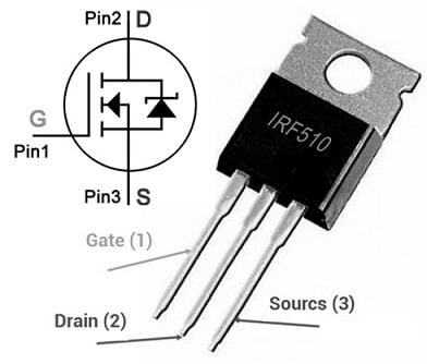
IRF510 MOSFET pin configuration is shown below. This MOSFET includes three pins which are discussed below.

IRF510 MOSFET Pin Configuration
- Pin-1 (Gate): This terminal is used to control the MOSFET biasing.
- Pin-2 (Drain): This terminal allows the flow of current.
- Pin-3 (Source): Current flows out throughout this terminal.
Features & Its Specifications:
IRF510 MOSFET features and its specifications include the following.
- It is a N-channel power MOSFET.
- This MOSFET includes three terminals.
- It is available in the TO-220 package.
- It has a Dynamic dv/dt rating.
- This transistor is single-pulse avalanche rated.
- Ease of paralleling.
- It has a high input impedance.
- This MOSFET has less thermal resistance.
- It has a higher switching speed.
- The maximum applied voltage from the Drain terminal to the source is 100Volts.
- Its maximum gate-to-source voltage must be ±20Volts.
- Its maximum continuous drain current is upto 5.6Amps.
- Maximum pulsed drain current is around 20Amps.
- Its maximum power dissipation is 43 watts.
- The minimum required voltage to conduct ranges from 2V to 4V.
- Its maximum storage and operating temperature ranges from -55 to +170 Celsius.
Equivalent & Alternatives
Equivalent IRF510 MOSFETs are; IRF120, IRF122, IRF512, IRF520, IRF522, IRF532 and IRF634. Alternative MOSFETs are; IRF513 with 80V drain-source voltage, IRF511 with 80V drain-source voltage, 2SK2399, 2SK551, BUK452-100A, BUK442-100B, BUK452-100B, IRFI520G, MTP10N10E, IRFS521 & IRF634.
How to use IRF510 MOSFET in a Circuit for a Long Time?
To get long-term performance in a circuit with IRF510 MOSFET, it is recommended to utilize it at least below 20% from its highest ratings. So its maximum drain current is 5.6Amps thus do not drive any load > 4.5Amps. The max drain to source voltage is around 100V for securely staying below 80Volts. Thus, the Gate to source voltage should not be raised from ±20Volts. Utilize a suitable heat sink with this transistor. Always operate and store this MOSFET in temperatures from -55 to +175 Centigrade.
Flyback Driver Circuit with 555 IC and IRF510 MOSFET
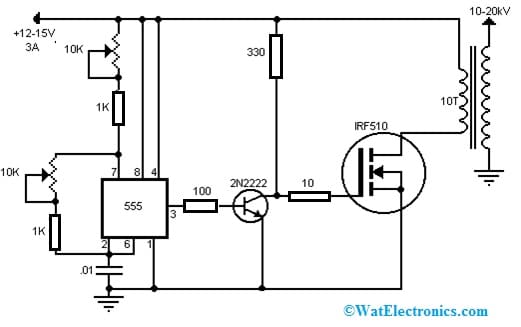
The Flyback driver circuit with 555 IC and IRF510 MOSFET is shown below. It is one kind of transformer that produces high-voltage signals to power computer monitors & CRT TVs. The required components to make this circuit mainly include; 10K potentiometers, 1K, 100 ohms and 10 Ohms resistors, 555 IC, IRF510 MOSFET, 2N2222 transistor, 10 to 20kV 10T transformer, +12V to 15V at 3A & 0.1uF capacitor. Connect the circuit as per the diagram shown below.

Flyback Driver Circuit with 555 IC and IRF510 MOSFET
Working
This flyback driver circuit works from +12VDC to +15VDC at about 3Amps. It stores energy within the magnetic field of the transformer in one half of a switching cycle, after that it releases to the secondary winding in the other half. So this is an efficient flyback driver circuit that uses a 555 IC to pulse a 2N2222 transistor through a square wave at a set frequency by the capacitor as well as the potentiometers.
After that 2N2222 transistor drives the gate terminal of the MOSFET which delivers the pulse to the 10-turn winding on the flyback. The potentiometers in the circuit can be adjusted to get the longest arc. The MOSFET in this circuit must be heatsinked. If the MOSFET still burns up or is too hot then you can put a 4 ohm or a 5 ohm resistor in between the source terminal of the MOSFET as well as the primary winding on the flyback. Ensure that these resistors have the correct power rating mainly for the voltage & current that they will be holding. Thus, the flyback must be wound by ten turns of 14 to 16-gauge solid wire.
1000Watts MOSFET Amplifier Circuit with MOSFETs
Power & efficiency are significant factors in audio amplification to decide the produced sound quality. So, MOSFET amplifiers have gained more popularity because of their capability to deliver high power outputs through less distortion.
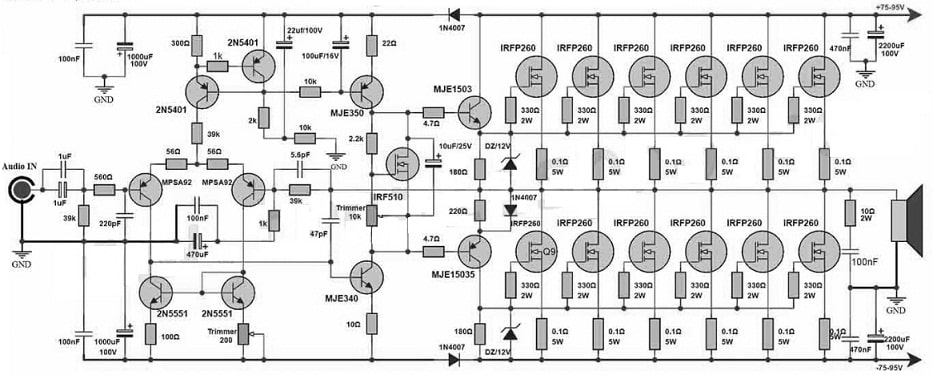
Here we are designing a 1000Watts MOSFET amplifier circuit with IRFP260 MOSFETs in the output section, transistors like; IRF510, MJE15034, MJE340, MJE15035, MJE350, MPSA92, 2N5551 & 2N5401 in the driver & preamplifier sections. Generally, powerful MOSFETs handle high power & current to make it the perfect choice for the output section. It ensures very efficient power delivery & reduced distortion due to its low on-resistance & fast switching speed characteristics.
The required components to make this MOSFET amplifier circuit mainly include; IRFP260 MOSFET and IRF510 MOSFET, transistors like; MJE15034, MJE15035, MJE340, MJE350, 2N5401, MPSA92, 2N5551, 1N4007 Diode, 63V power supply and 12V Zener Diodes. Connect this circuit as per the diagram shown below.

1000Watts MOSFET Amplifier Circuit with MOSFETs
Working
This amplifier circuit involves two sections like driver & preamplifier which use different transistors. The driver stage in this circuit uses MJE15034 & MJE15035 transistors which deliver high voltage gain as well as current amplification. So these transistors work in combination to amplify the received weak input signal from the preamplifier section.
The preamplifier section uses MJE350, MJE340, IRF510, MPSA92, 2N5401 and 2N5551 transistors. So these transistors play a significant role in improving the audio signals from the low level that comes from the audio source. So they jointly amplify and shape the incoming audio signal to a suitable level for the driver stage. Further, it amplifies and drives the IRFP260 MOSFET transistors within the output stage. Thus, this amplifier circuit delivers superior audio performance to make it an excellent choice mainly for audiophiles.
Advantages & Disadvantages
The IRF510 MOSFET advantages include the following.
- IRF510 MOSFET offers quick switching.
- It has a low on-resistance.
- It is rugged and cost-effective.
- This MOSFET has less thermal resistance.
- It has a lower package cost.
- This MOSFET is designed mainly for applications that need low gate and high-speed drive power.
- It can be directly operated from microcontrollers, ICs, and several electronic platforms like; Raspberry Pi, Arduino, etc because of its lower gate power requirements.
The IRF510 MOSFET disadvantages include the following.
- These are vulnerable to harm from electrostatic charges due to their slight oxide layer.
- Its gate pin is particularly sensitive to static electricity.
- They can become unstable whenever overloaded by voltage.
- These can overheat, which limits their power-handling ability.
- They have quite slow switching speeds, thus it can make them inefficient within high-frequency-based circuits.
- Hot-carrier degradation occurs whenever a non-zero voltage is provided at the drain terminal.
Applications
The IRF510 MOSFET applications include the following.
- IRF510 MOSFET is used in normal & high-speed applications like; UPS, DC to DC converters, power supplies, and many more.
- This MOSFET drives high-power relay switches with extremely high-power or low-power transistors (or) any application that needs speed switching including less gate power.
- This MOSFET can also be utilized to design high-power audio amplifier circuits.
- It can also be utilized as a separate amplifier for driving speakers.
- It is used for fast switching, UPS, management systems, battery chargers, solar UPS, motor driver circuits, solar battery chargers, telecommunication, and computer applications.
Please refer to this link for the IRF510 MOSFET Datasheet.
Thus, this is an overview of IRF510 MOSFET, pinout, features, specifications, circuit, working advantages, disadvantages, and applications. IRF510 is a high-speed N-Channel power MOSFET including up to 5.6Amps output load capability & up to 100V load voltage. This MOSFET is designed mainly for applications like; switching converters, relay drivers, switching regulators, motor drivers & drivers for higher-power bipolar-based switching transistors which require low gate and higher-speed drive power. These MOSFETs can be operated from integrated circuits directly. Here is a question for you, what is JFET?